Mixing device for a discharge unit

a discharge unit and mixing device technology, applied in the direction of liquid transfer devices, infusion syringes, transportation and packaging, etc., can solve the problems of known static mixers, relatively large dead volume, unsatisfactory mixing of substances, etc., and achieve the effect of simple and cost-efficient mixing

Inactive Publication Date: 2016-06-28
MEDMIX SWITZERLAND AG
View PDF32 Cites 2 Cited by
  • Summary
  • Abstract
  • Description
  • Claims
  • Application Information

AI Technical Summary

Benefits of technology

[0009]It is, therefore, an object of the present, invention to provide a mixing device which can be connected to a discharge unit and which ensures sufficient mixing in particular of small quantities of low-viscosity substances with as small a dead volume as possible. The mixing device should additionally comprise a compact design and should be able to be produced in as simple and cost-efficient a manner as possible.
[0011]This type of development of the mixing device allows it to mix in particular low-viscosity substances in an optimum manner with one another inside the mixing structure at a minimum dead volume even in the case of small volumes. As a result of the mixing device comprising a base element and an insert part which can be inserted therein, the mixing device can be produced in a very cost-efficient and in particular compact manner.
[0019]Preferably, the mixing structure is realized in the form of indentations in the outside wall of the insert part and is designed in this case in particular in a groove-shaped manner. The mixing channels are then formed, therefore, by indentations or grooves which are realized on the outside surface of the insert part. Preferably, the mixing structure comprises a maximum depth which is not greater than half, more preferred than a third, of the radius of the insert part if the insert part is designed in a substantially cylindrical manner. The dead volume of the mixing device can be kept very small in particular in this way.
[0026]Preferably, the mixing structure comprises at least three, in particular at least five and most preferably even more than eight pairs of channels, which extend separately from one another, and preferably at least three, in particular at least five and most preferably even more than eight mixing zones into which, in each case, one pair of the two channels, which extend separately from one another, open out. The mixing of the substances can be further improved as a result;

Problems solved by technology

The majority of these known static mixers, however, are unsuitable for low-viscosity liquids as well as in the case of small volumes and low flow rate because too few turbulent flows are generated and consequently the mixing of the substances can be unsatisfactory.
In addition, in the case of the conventional mixers the dead volumes are relatively large.
In the case of substances which react quickly with one another, there is the additional problem of a chemical reaction being able to take place even in the interior of the mixing device, as a result of which the substances can become “blocked” in the mixing device.
Sufficient mixing, however, is not ensured in the case of the mixing devices disclosed in said documents either, in particular in the case of small volumes and where the flow rate of the substances to be mixed is low.
The dead volume generated in said device, however, is relatively large.

Method used


Image

  • Mixing device for a discharge unit
  • Mixing device for a discharge unit
  • Mixing device for a discharge unit

Examples


Embodiment Construction

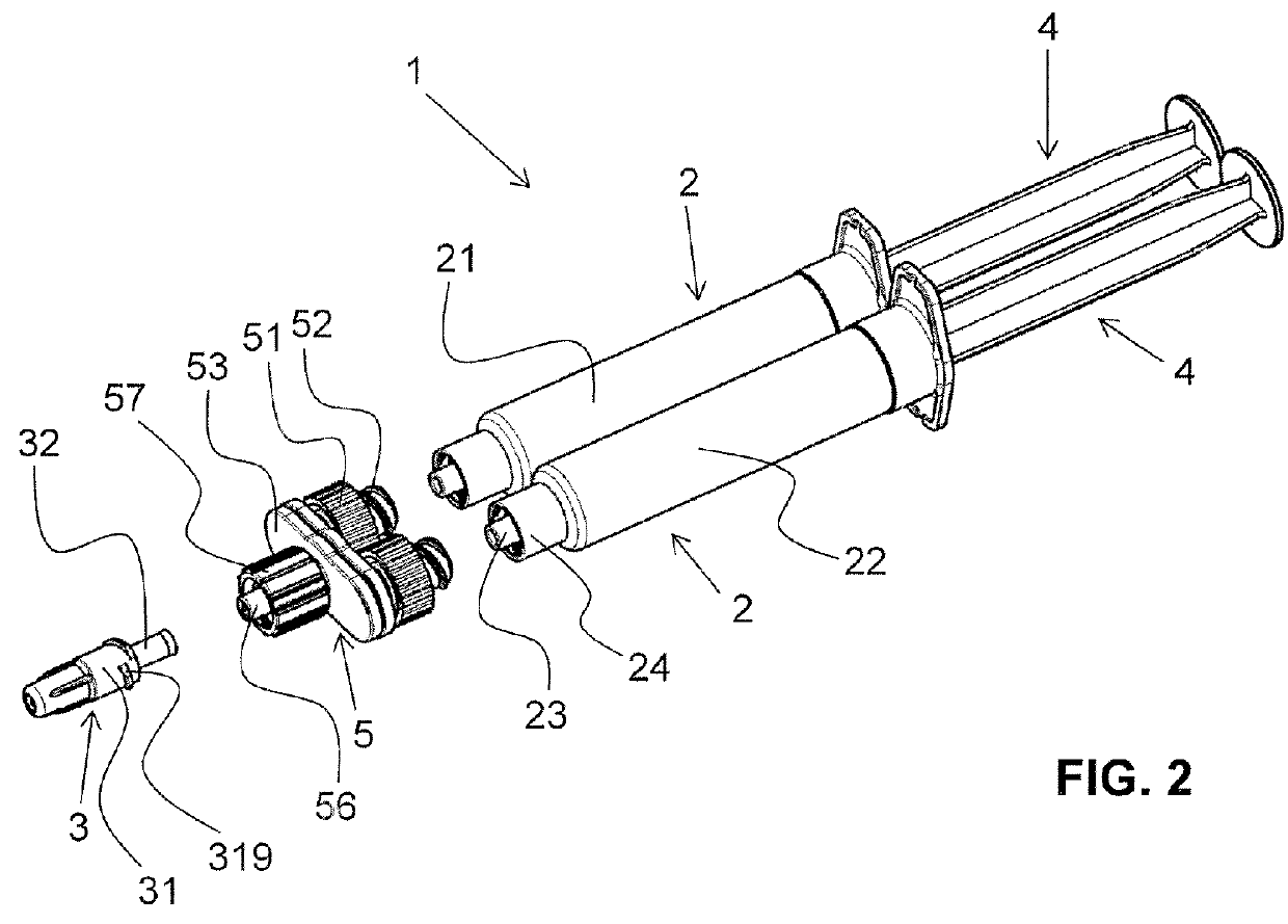
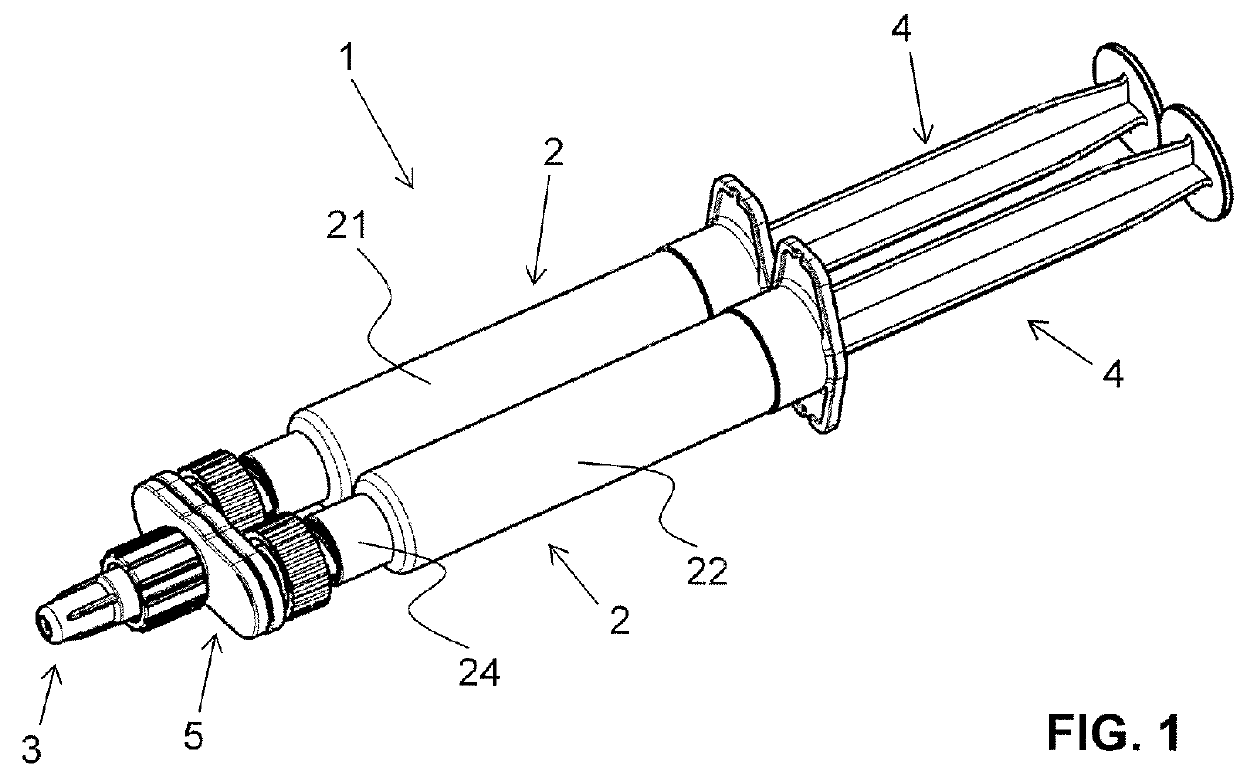
[0054]FIGS. 1 to 10 show a mixing device according to a first embodiment according to the invention. The mixing device is realized in this embodiment as a spray head 3 and is connected via a connection part 5 to two individual syringes 2 which are connected together. The individual syringes 2, together with the connection part 5, form a discharge unit 1. By means of the connection part 5, the two distal outputs of the individual syringes 2 are brought together to form one single Luer connector 56 to which the spray head 3 can be connected. The spray head 3 serves in particular for mixing and atomizing the substances contained in the discharge unit 1.

[0055]The discharge unit 1 comprises, as is shown in FIGS. 1 to 5, two reservoirs 21 and 22 which are arranged in parallel and which serve for storing each of the different substances which are to be mixed together directly prior to the application or the discharging. In order to discharge the two substances preferably at the same time i...


PUM


Abstract

A mixing device which can be connected to a discharge unit and is provided to mix one or more substances together as they are discharged from the discharge unit. The mixing device has a base element with a circumferential side wall and an insert which can be inserted into the base element in such a manner that at least one circumferential zone of said insert lies against the side wall of the base element in a sealing manner. A mixing structure with mixing channels is formed on the insert, through which mixing structure the substances can be discharged from the discharge unit.

Description

CROSS REFERENCE TO RELATED APPLICATIONS[0001]This is a National Stage of International Application No. PCT / CH2013 / 000121 filed Jul. 9, 2013, claiming priority based on Swiss Patent Application No. 01432 / 12 filed Aug. 21, 2012, the contents of all of which are incorporated herein by reference in their entirety.TECHNICAL SCOPE[0002]The present invention relates to a mixing device which is connectable to a discharge unit and which, when one or more substances are discharged from the discharge unit, serves for mixing said substances. The mixing device is in particular a static mixer. The invention also relates to a set comprising a discharge unit and a mixing device of this type.PRIOR ART[0003]Mixing devices and in particular so-called static mixers are often used in medical applications but also in other applications in order to mix two or even more substances together when they are discharged from a discharge unit. The substances to be mixed together, in this case, are usually stored ...

Claims


Application Information

Patent Timeline
Patent Type & Authority Patents(United States)
IPC IPC(8): B67D7/78B01F13/00B01F5/06B01F15/02B05C17/005A61M5/19A61B17/00B01F5/00
CPCB01F15/0237B01F5/0645B01F5/0661B01F13/0023B05C17/00553B05C17/00593A61B2017/00495A61M5/19B01F2005/0022B05C17/00503B01F2025/915B01F25/43231B01F25/434B01F33/50112B01F35/7174B01F25/44
Inventor GRETER, ANDYFURRER, MANUELVEID, MARTIN
Owner MEDMIX SWITZERLAND AG
Why Eureka
Try Eureka