
Disk drive suspension having dual vibration damper

a technology of vibration damper and disk drive, which is applied in the direction of arm assembly structure, instruments, data recording, etc., can solve the problems of disc drive vibration within the disk drive, off-track errors at the head suspension, sources of vibration, etc., and achieve effective damping, effective damping, effective damping

Active Publication Date: 2016-06-14
MAGNECOMP
View PDF17 Cites 5 Cited by
  • Summary
  • Abstract
  • Description
  • Claims
  • Application Information

AI Technical Summary

Benefits of technology

The patent describes a special design that uses two layers of viscoelastic damping material with different properties and geometries. These layers work together to provide effective damping at different temperatures and frequencies. This design allows for resonant mode damping, which can be useful in various applications such as reducing vibrations or improving control. The two layers can also be designed to have different peak attenuation and peak attention frequencies, making them more versatile and effective damping materials.

Problems solved by technology

The spinning disk causes vibrations within the disk drive.
Other sources of vibration exist within an operating disk drive including windage.
The vibration can cause off-track errors at the head suspension.

Method used


Image

  • Disk drive suspension having dual vibration damper
  • Disk drive suspension having dual vibration damper
  • Disk drive suspension having dual vibration damper

Examples


Embodiment Construction

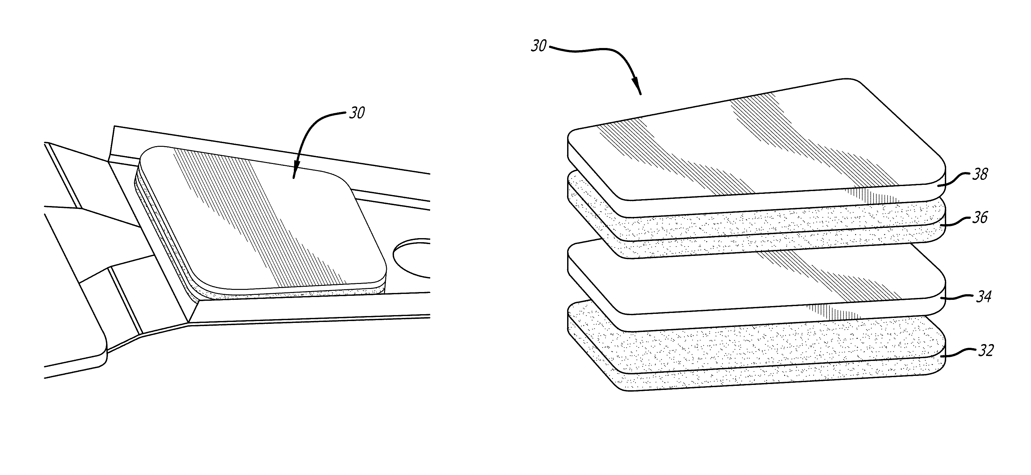
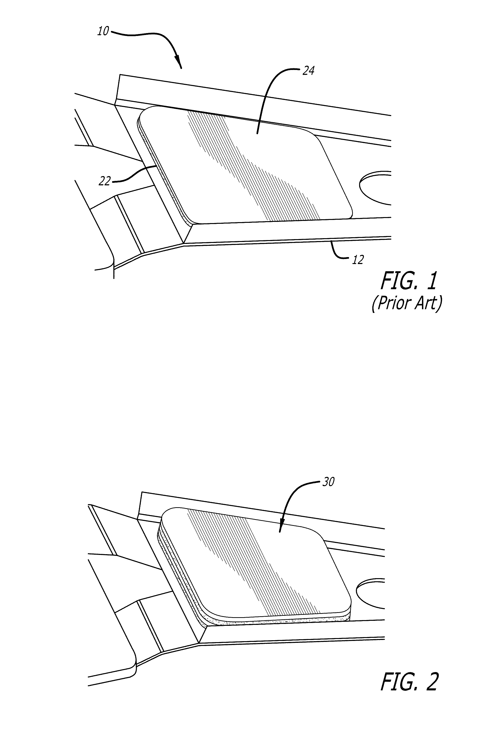
[0018]FIG. 2 is a top perspective view of a suspension 10 including a dual vibration damper 30 according to an exemplary embodiment of the invention. The dual damper configuration was originally developed to test the feasibility of cutting thicker material than the material that is conventionally used for vibration dampers, and the resulting damping effect on the head gimbal assembly (HGA). As can be seen in FIG. 3, which is a scanning electron microscope (SEM) photograph of a dual vibration damper 30 according to the embodiment of FIG. 2, clean cutting of the laminated material to form the damper is feasible.

[0019]FIG. 4 is an exploded view of the dual vibration damper 30 of FIG. 2. Dual vibration damper 30 includes a first damping layer 32, a first constraint layer 34 thereon, then a second damping layer 36, and finally a second constraint layer 38, the layers being vertically stacked.

[0020]Damping layers 32 and 36 can comprise two different materials and / or different material pro...


PUM


Abstract

A vibration damper for a suspension has two different viscoelastic layers and two different constraint layers. The two viscoelastic layers can be tailored to have different properties, including different viscosities and / or peak vibration frequency damping at different frequencies. The vibration damper exhibits improved vibration damping as compared to a single layer damper having the same overall thickness at critical frequencies.

Description

CROSS-REFERENCE TO RELATED APPLICATIONS[0001]This application claims benefit of U.S. provisional patent Application No. 62 / 030,420 filed Jul. 29, 2014, which is incorporated by reference as if set forth fully herein.BACKGROUND OF THE INVENTION[0002]1. Field of the Invention[0003]This invention relates to the field of disk drive suspensions. More particularly, this invention relates to the field of a disk drive suspension having a dual vibration damper.[0004]2. Description of Related Art[0005]Disk drives such as magnetic hard disk drives for memory storage spin at speeds of up to 10,000 RPM. The spinning disk causes vibrations within the disk drive. Other sources of vibration exist within an operating disk drive including windage. The vibration can cause off-track errors at the head suspension. There is therefore a need to minimize vibration at the head suspension in order to minimize off-track errors.[0006]Vibration dampers for the purpose of reducing vibration of the head suspensio...

Claims


Application Information

Patent Timeline
IPC IPC(8): G11B3/12G11B3/18G11B5/48
CPCG11B3/18G11B3/124G11B3/12G11B5/4833
Inventor HAHN, PETERMISUTA, STEVE
Owner MAGNECOMP
Learn More