Optical force sensor and apparatus using optical force sensor
a technology of optical force sensor and optical force sensor, which is applied in the direction of force measurement by measuring optical property variation, instruments, fluid pressure measurement, etc., can solve the problems of difficult to provide a sufficient sensitivity to detect displacement and the likely influence of disclosed force sensor, so as to reduce thickness, reduce sensor stiffness, and highly sensitive detection
- Summary
- Abstract
- Description
- Claims
- Application Information
AI Technical Summary
Benefits of technology
Problems solved by technology
Method used
Image

Examples
embodiment 1
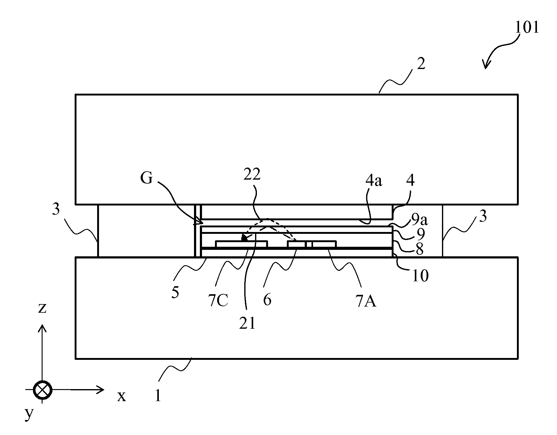
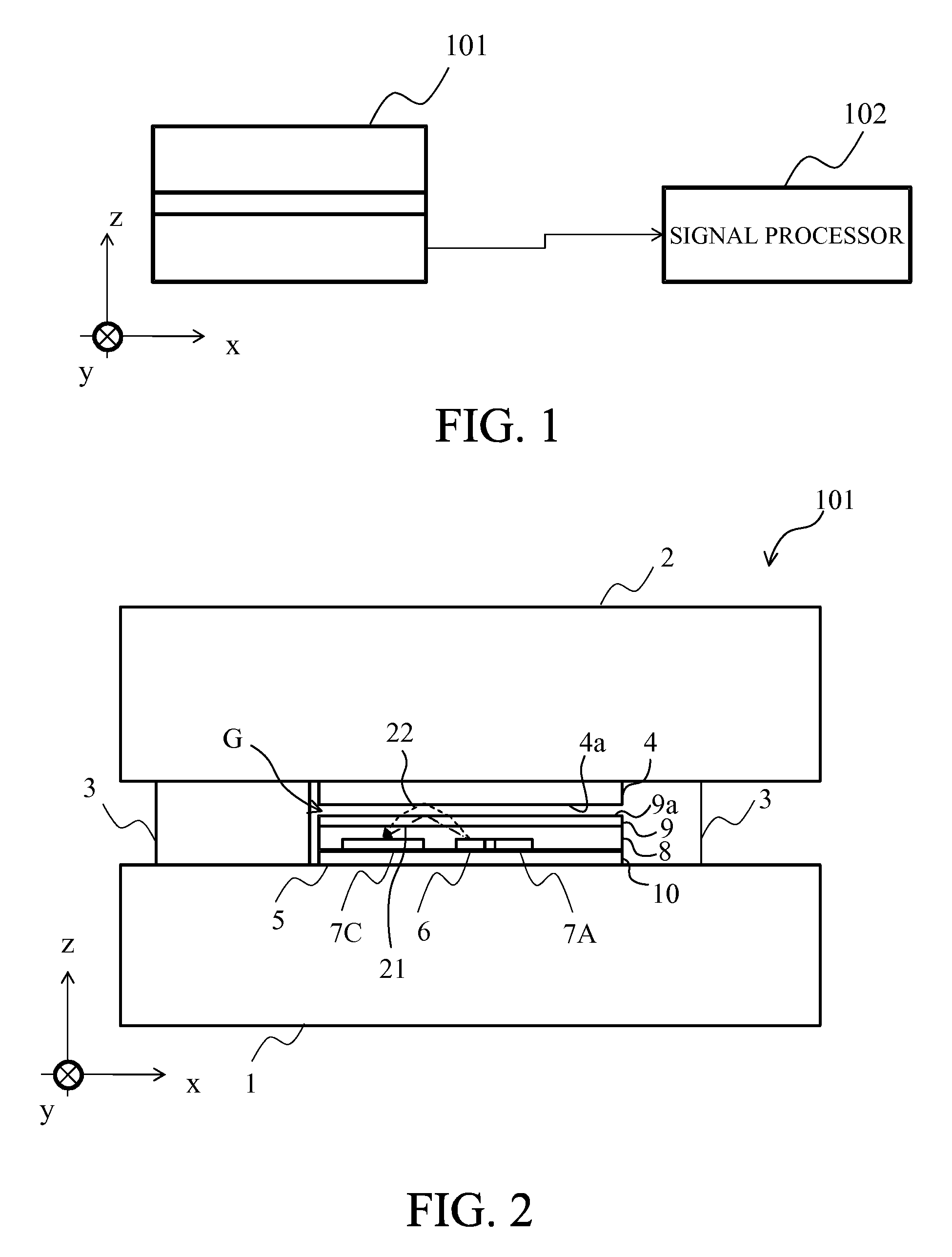
[0021]FIG. 1 illustrates a configuration of an optical force sensor that is a first embodiment (Embodiment 1) of the present invention. The force sensor is constituted by a sensor unit 101 and a signal processor 102 serving as a first calculator. The sensor unit 101 outputs, to the signal processor 102, a displacement signal indicating a displacement of a displaceable member (described later) in the sensor unit 101, the displacement being caused by an external force. The signal processor 102 calculates a vector amount of the external force from the input displacement signal and outputs a calculation result as a force signal.
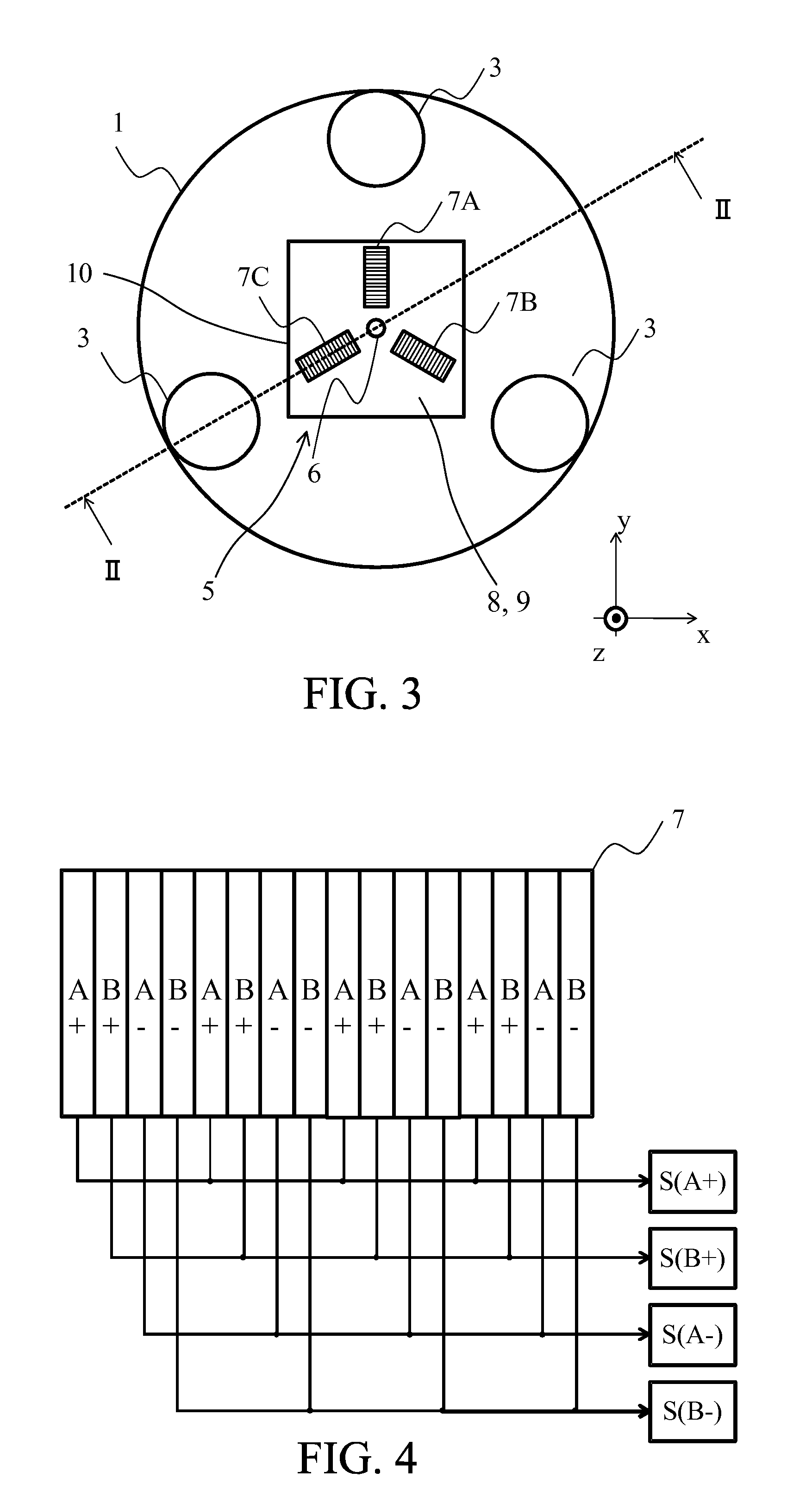
[0022]FIG. 2 illustrates a side section of the sensor unit 101 viewed from a direction of a y-axis (hereinafter referred to as “a y-axis direction”), and FIG. 3 illustrates a z-axis cross-section of the sensor unit 101. FIG. 2 illustrates a section of the sensor unit 101 cut along a II-II line in FIG. 3.
[0023]The sensor unit 101 is constituted by a base member 1,...
embodiment 2
[0042]FIG. 5 illustrates a configuration (z-axis cross-section similar to FIG. 3) of a sensor unit 101A of an optical force sensor that is a second embodiment (Embodiment 2) of the present invention. This embodiment includes four elastic supporting members 3 whose number and arrangement are different from those in Embodiment 1 and four light-receiving element arrays 7A to 7C whose number and arrangement are different from those in Embodiment 1. In this embodiment, constituent elements identical to those in Embodiment 1 are denoted by the same reference numerals as those in Embodiment 1.
[0043]In this embodiment, the four elastic supporting members 3 are provided to the sensor unit 101A, and the four light-receiving element arrays 7A, 7B, 7C and 7D are provided to a displacement detector 5A. The four elastic supporting members 3 are arranged between the base member 1 and the displaceable member 2 at four 90-degree angularly-spaced positions surrounding the displacement detector 5A tha...
embodiment 3
[0049]FIG. 6 illustrates a configuration (side section) of a sensor unit 101B of an optical force sensor that is a third embodiment (Embodiment 3) of the present invention. FIG. 7 illustrates a z-axis cross-section of the sensor unit 101B. FIG. 6 illustrates a section of the sensor unit 101B cut along a VI-VI line in FIG. 7.
[0050]The sensor of this embodiment is capable of detecting six-axis external forces including the three-axis external forces that can be detected in Embodiment 1 and other three-axis external forces acting in in-surface directions of light-receiving surfaces of light-receiving-element arrays (hereinafter referred to as “in-light-receiving-surface directions”) corresponding to a second direction along the x- and y-axes. In this embodiment, constituent elements identical to those of Embodiment 1 are denoted by the same reference numerals as those in Embodiment 1.
[0051]In this embodiment, a displacement detector 5B of the sensor unit 101B is constituted by a detect...
PUM
| Property | Measurement | Unit |
|---|---|---|
| height | aaaaa | aaaaa |
| half-wavelength width | aaaaa | aaaaa |
| central wavelength | aaaaa | aaaaa |
Abstract
Description
Claims
Application Information
 - R&D Engineer
- R&D Manager
- IP Professional
- Industry Leading Data Capabilities
- Powerful AI technology
- Patent DNA Extraction
Browse by: Latest US Patents, China's latest patents, Technical Efficacy Thesaurus, Application Domain, Technology Topic.
© 2024 PatSnap. All rights reserved.Legal|Privacy policy|Modern Slavery Act Transparency Statement|Sitemap