
Mould for the rotational moulding of plastic materials

a technology of plastic materials and moulds, applied in the direction of coatings, etc., can solve the problems of manufacturing articles, possible formation of so-called “blowholes” in the mould, and the lack of insert-holding devices, etc., and achieve the effect of being convenient to use, cost-effective and particularly functional

Active Publication Date: 2016-05-31
PERSICO
View PDF10 Cites 0 Cited by
  • Summary
  • Abstract
  • Description
  • Claims
  • Application Information

AI Technical Summary

Benefits of technology

The present invention aims to provide a mold for the rotational molding of plastic materials that can prevent cracking in the manufactured article due to the formation of blowholes and application of pressure and / or vacuum. The device is simple, cost-effective, and functional.

Problems solved by technology

A typical drawback encountered in moulds provided with insert-holding devices is linked to the possible formation of the so-called “blowholes” around the co-moulded inserts.
This possible air passage creates cracking in the manufactured article and thus involves the need of discarding the manufactured article itself that must be remoulded, with an obvious waste of time and money.
Another drawback encountered in moulds provided with insert-holding devices is linked to the scarcity of polymeric material that manages to “coat” the insert itself.
Consequently, the insert-holding device is often penalised in receiving the heat irradiated by the oven.
This classical solution makes it complex to manage the heating of the mould in a differentiated manner, for example favouring the heating of certain areas of the mould.
, it is also technically difficult to apply external elements to the mould that allow the temperature to be detected, as well as the application of circuits through which it is possible to manage and control the internal pressure of the mould.
Indeed, at the communication points between the inside and the outside of the mould the pressure difference across the molten polymer leads to the cracking of the manufactured article, moving the material in such an area and generating a waste.

Method used


Image

  • Mould for the rotational moulding of plastic materials
  • Mould for the rotational moulding of plastic materials
  • Mould for the rotational moulding of plastic materials

Examples


Embodiment Construction

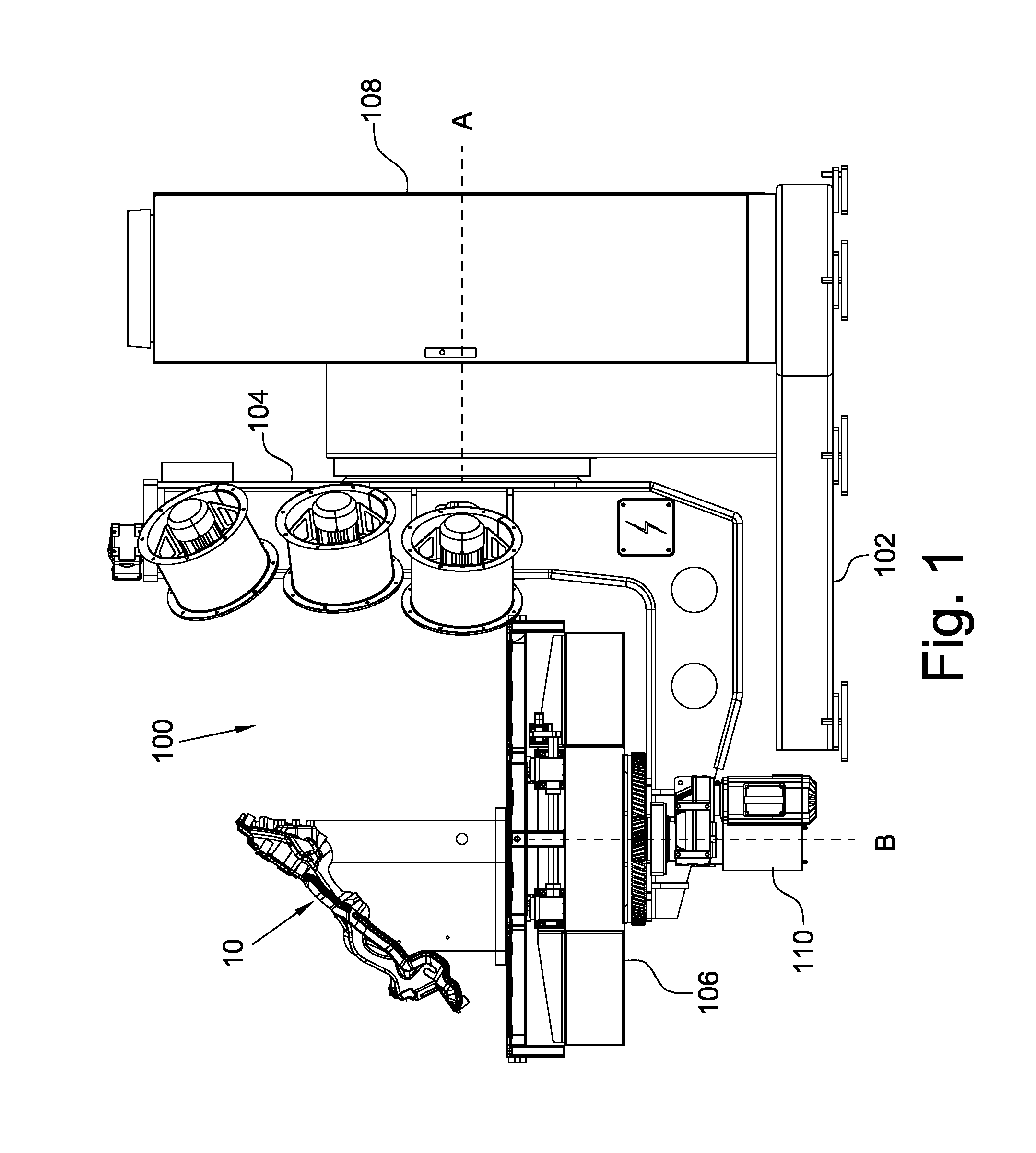
[0023]With reference in particular to FIG. 1, a generic machine 100 for the rotational moulding is shown, on which a mould 10 according to the present invention can be mounted. The machine 100 is of the type comprising a base frame 102 that supports a first movable frame 104 that can rotate about a first motorized axis A, for example horizontal. Inside the first movable frame 104 a second movable frame 106 is supported that can rotate about a second motorized axis B, for example vertical, orthogonal to the first motorized axis A. On the second movable frame 106 the mould 10 is mounted, so that it can rotate about the motorized axes A and B. Respective motors 108 and 110 drive the rotation of the movable frames 104 and 106 about the two corresponding axes A and B.

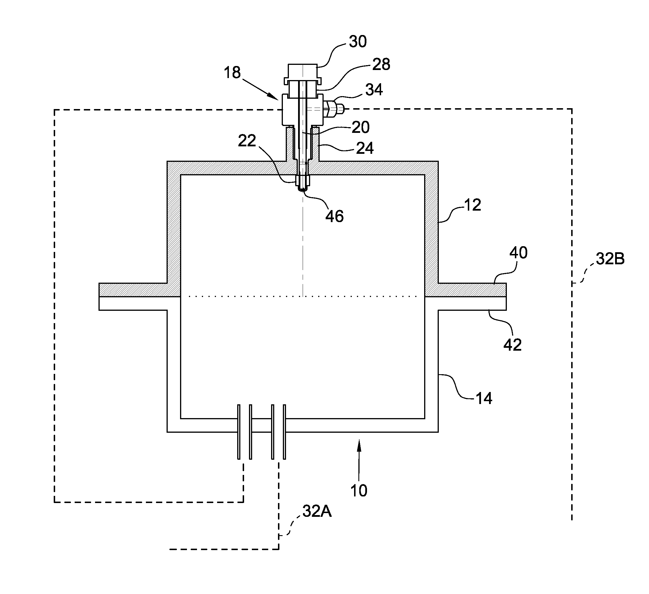
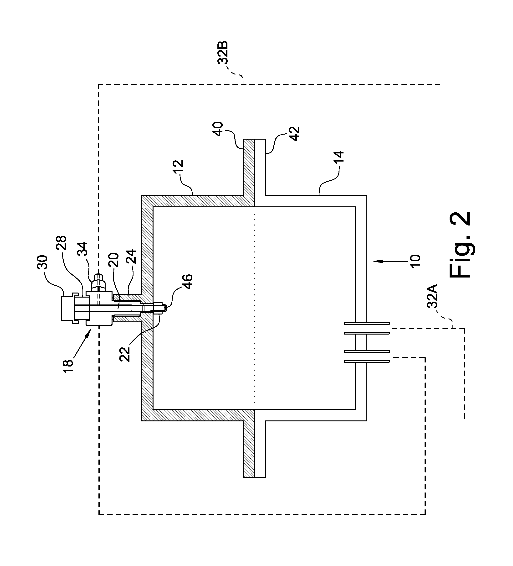
[0024]Inside the second movable frame 106 the mould 10 is mounted (FIGS. 2 and 3), which comprises two half-moulds 12 and 14. At least one of the two half-moulds 12 and 14 is provided with one or more heating elements 16, li...


PUM

PropertyMeasurementUnit
temperatureaaaaaaaaaa
pressureaaaaaaaaaa

Abstract

A mold for the rotational molding of manufactured articles of plastic material includes two half-molds, one of which is provided, on its surface, with an insert-holding device comprising a rod with a first end passing through the wall of the half-mold at a respective passage channel and axially movable for projecting inside the mold. The mold also comprises a first pneumatic circuit able to apply a predetermined pressure, positive or negative, inside the mold. At least one insert-holding device is operatively connected to a second pneumatic circuit able to apply a predetermined pressure, positive or negative, and is internally provided with a plurality of means to apply the predetermined pressure at the passage channel, so that at the insert-holding device the same predetermined pressure value which generates inside the mold by the first pneumatic circuit is applied.

Description

FIELD OF THE INVENTION[0001]The present invention refers in general to a mould for the rotational moulding of plastic materials and, more specifically, to a device for fixing inserts in a mould for the rotational moulding of plastic materials.BACKGROUND OF THE INVENTION[0002]As known, the moulding technology called “rotational” is dedicated to the production of hollow manufactured articles starting from various polymers. The rotational moulding technology provides the use of a specific mould in which a predetermined amount of liquid or powdered plastic is arranged. After the mould is closed, it is rotated about two perpendicular axes and heated, so that the hot material stratifies on the walls of the mould itself. Once the process has ended, the mould is cooled and, after reopening, the moulded piece or manufactured article is removed.[0003]In many moulded pieces or manufactured articles there is the need to apply, during the moulding step, one or more inserts configured to face fro...

Claims


Application Information

Patent Timeline
Patent Type & Authority Patents(United States)
IPC IPC(8): B29C41/04B29C41/50B29C41/06B29C41/20B29C33/12B29C41/38B29C41/52B29C33/18
CPCB29C41/20B29C33/12B29C41/04B29C41/042B29C41/38B29C41/50B29C41/52B29C33/18
Inventor PERSICO, CLAUDIABERGAMO, LORENZO
Owner PERSICO
Learn More