
Anthropometric measuring device

a technology of measuring device and anthropometric, applied in the field of measuring device, can solve the problems of relatively complex tension measuring device and change of tension

Active Publication Date: 2016-05-31
WOLVERINE OUTDOORS
View PDF19 Cites 1 Cited by
  • Summary
  • Abstract
  • Description
  • Claims
  • Application Information

AI Technical Summary

Benefits of technology

The present invention is an anthropometric measuring device with a measuring tape and a one-piece handle. The handle has a fixed reference and a movable reference that can move when the measuring tape is subjected to tension. The device also includes a resilient element that allows the movable reference to move into alignment with the fixed reference when the measuring tape is under the proper tension. This allows the resilient element to return to its original shape and provides uniformity of result during repeated uses. The fixed reference can be supported by an arm extending from the main body of the handle or two arms extending from the main body of the handle. The arms can be configured so that the fixed indicators are disposed on opposite sides of the measuring tape, thereby providing opposed indicators that can help to ensure that the measuring tape is pulled straight and not on an angle with respect to the handle. The one-piece handle is easy to use and includes a single fixed reference for tension and size, which simplifies the user experience and ensures accurate measurements. Opposed fixed indicators simultaneously show the tension and measurement markings, making it easier to use the device and ensuring uniform application of force to the resilient elements.

Problems solved by technology

This creates some difficulty as it is possible that the tension will change while the user is moving focus from the tension measuring device scale to the measuring tape graduations.
In addition to presenting practical difficulties in use, the tension measuring device is relatively complex having a plurality of different parts that are separately manufactured and assembled to form the complete unit.

Method used


Image

  • Anthropometric measuring device
  • Anthropometric measuring device
  • Anthropometric measuring device

Examples


Embodiment Construction

[0027]Overview.

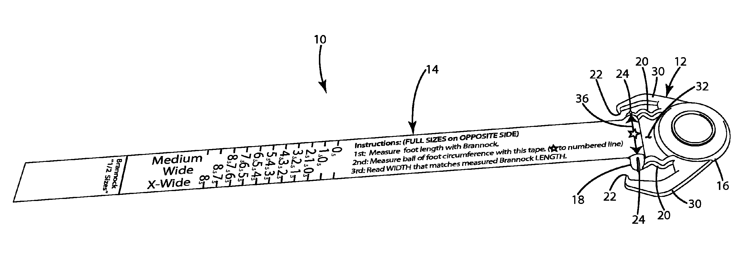
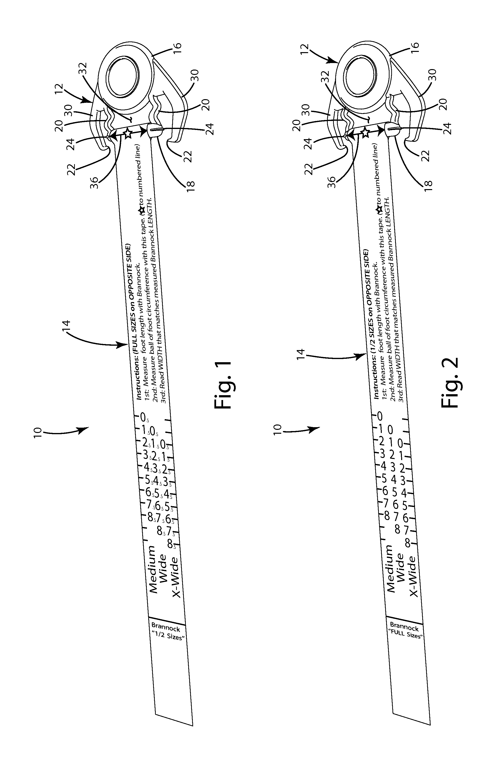
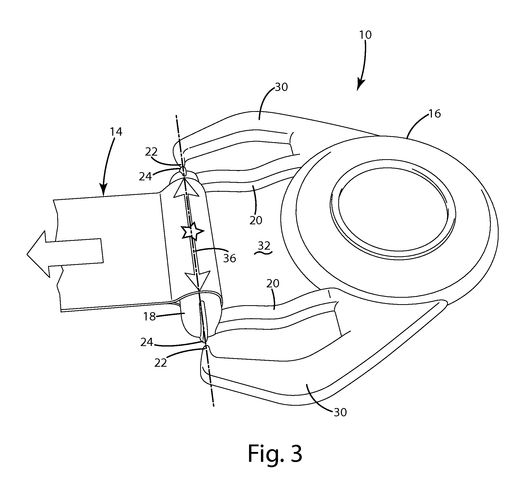
[0028]An anthropometric measuring device in accordance with an embodiment of the present invention is shown in FIGS. 1 and 2. The measuring device 10 generally includes a one-piece handle 12 and a measuring tape 14. In use, the measuring device 10 is intended to provide uniform measurements by allowing measurements to be taken with the measuring tape 14 held under uniform tension. The handle 12 includes a main body 16 that can be held by the user and an anchor portion 18 on which the measuring tape 14 is secured. The anchor portion 18 is joined to the main body 16 by one or more resilient elements 20. The resilient elements 20 are configured to undergo controlled deformation when the measuring tape 14 is placed under tension (See FIG. 3). The handle 12 includes a fixed reference 22 carried by the main body 16 and a movable reference 24 carried by the anchor portion 18. The fixed reference 22 and the movable reference 24 are arranged to align when the measuring tape 14...


PUM


Abstract

A measuring device with a measuring tape and a one-piece handle. The handle includes a main body with a fixed reference, an anchor portion with a movable reference and a resilient element. The measuring tape is secured to the anchor portion. The resilient element allows the anchor portion to move with respect to the main body when the measuring tape is under the tension. The resilient element is configured so that the movable reference comes into alignment with the fixed reference when the measuring tape is under proper tension. The fixed reference may also provide a reference from which to take measurements. The resilient element may include a pair of nonlinear segments that straighten under tension. The main body may include a pair of fixed references disposed on opposite sides of the measuring tape, and the anchor portion may include a pair of corresponding movable references.

Description

BACKGROUND OF THE INVENTION[0001]The present invention relates to measuring devices and more particularly to measuring devices that operate under tension.[0002]Anthropometric measuring devices are often used to measure the dimension of various parts of the human body. For example, anthropometric measuring devices can be used to measure foot circumference for use in determine footwear width or can be used to measure chest circumference for use in determining coat or shirt size. A typical anthropometric measuring device includes a flexible measuring tape that is graduated in essentially the same manner as a ruler. In use, the flexible measuring tape can be wrapped circumferentially around the part to be measured and then back onto itself to provide the measurement. In many anthropometric applications, the body part being measured will have relatively soft tissue that can be compressed if the measuring tape is wrapped under tension. This means that the circumferential measurement can v...

Claims


Application Information

Patent Timeline
Patent Type & Authority Patents(United States)
IPC IPC(8): G01B3/10A43D1/02A61B5/107A61B5/00G01B3/00
CPCA61B5/1074A43D1/02A61B5/6829G01B3/004G01B3/10A41H1/02A43D1/027A43D1/04
Inventor WOJCIESZAK, CRAIG M.TELEEN, MATTHEW F.
Owner WOLVERINE OUTDOORS
Learn More