Method for making a motor quieter

a motor and quiet technology, applied in the direction of single motor speed/torque control, controller with pulse-train output signal, liquid fuel engine, etc., can solve the problem of weak motor when operating at a low rpm, undesirable clicking noise in the stator winding of the coil, etc. problem, to avoid the noise problem, click noise, and unwanted clicking or snapping noise

Active Publication Date: 2016-05-17
LD DESIGN ELECTRONICS
View PDF4 Cites 0 Cited by
  • Summary
  • Abstract
  • Description
  • Claims
  • Application Information

AI Technical Summary

Benefits of technology

[0020]The method for making a motor quieter includes the step of sending a pulse width modulated (PWM) signal to a first transistor. The first transistor conducts current into a stator winding. A second transistor is switched to by sending the PWM signal to the second transistor instead to the first transistor. The first transistor terminates conduction of the current into the stator winding and induces transients in the stator winding. A capacitor suppresses the transients induced by the first transistor. A non-polarized electrolyte capacitor is used to suppress noise from transients and a diode to set a voltage limit of the capacitor. A zener diode sets a voltage limit of the non-polarized electrolyte capacitor.

Problems solved by technology

Nevertheless, brushless fan motors when operated, and when the stator energized electro-magnetic coils change polarization, an unwanted clicking or snapping noise can be heard particularly when the revolving fan blades do not override the clicking noise made by the fan motor.
When the rpm of the motor is only controlled by the variation of the voltage, the motor becomes weak when operating at a low rpm.
Rapid openings of the transistors, i.e. when the PWM pulses are not truncated, results in the sudden flow of current through the stator windings, which creates the undesirable clicking noise in the stator windings of the coil.
If only the coil inductance is used to limit the increase of the current, then the current rushes into the coil too fast and causes the undesirable clicking noise in the stator windings.
The sensor thus determines how fast the motor rotates but it does not necessarily determine at what rpm the motor should rotate.

Method used


Image

  • Method for making a motor quieter
  • Method for making a motor quieter
  • Method for making a motor quieter

Examples


Embodiment Construction

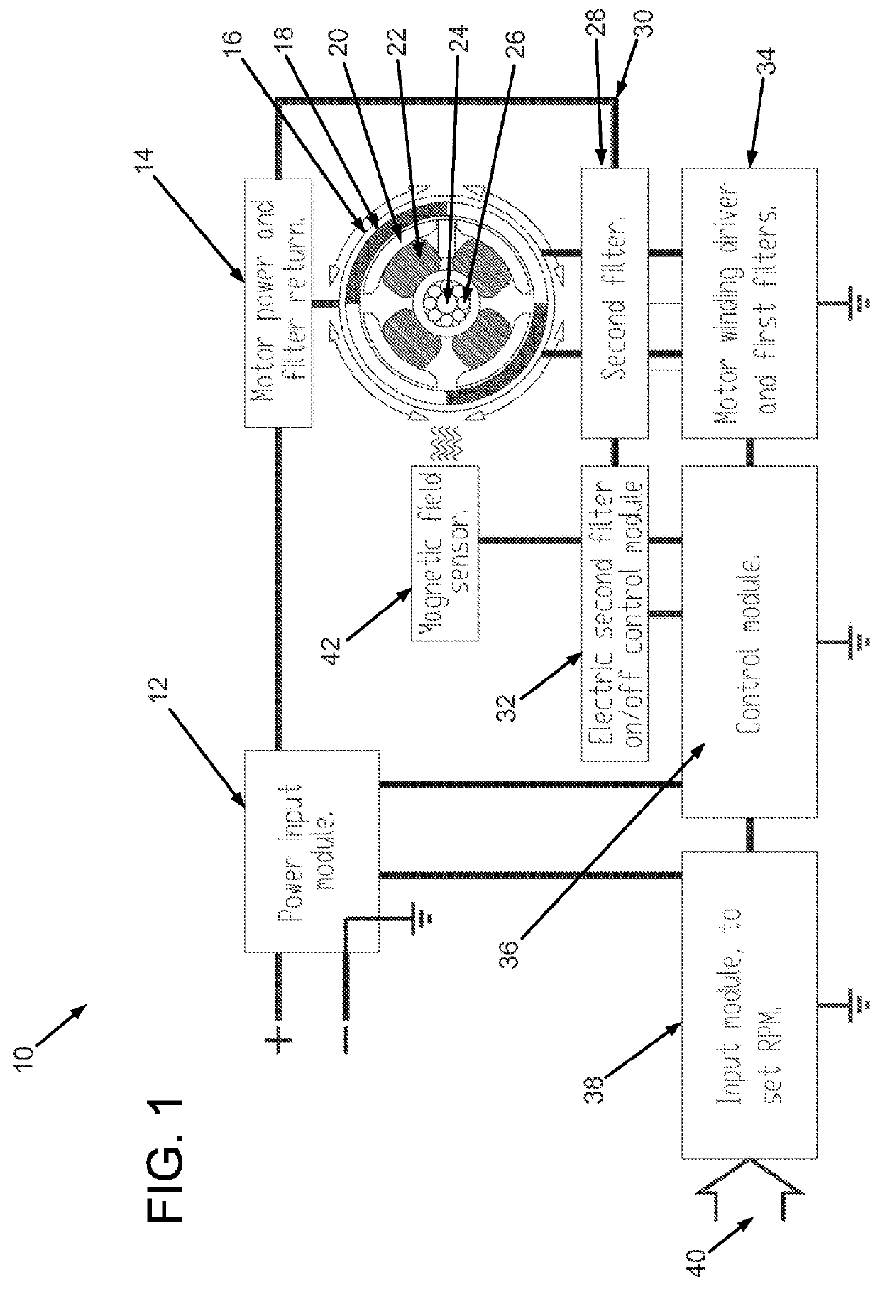
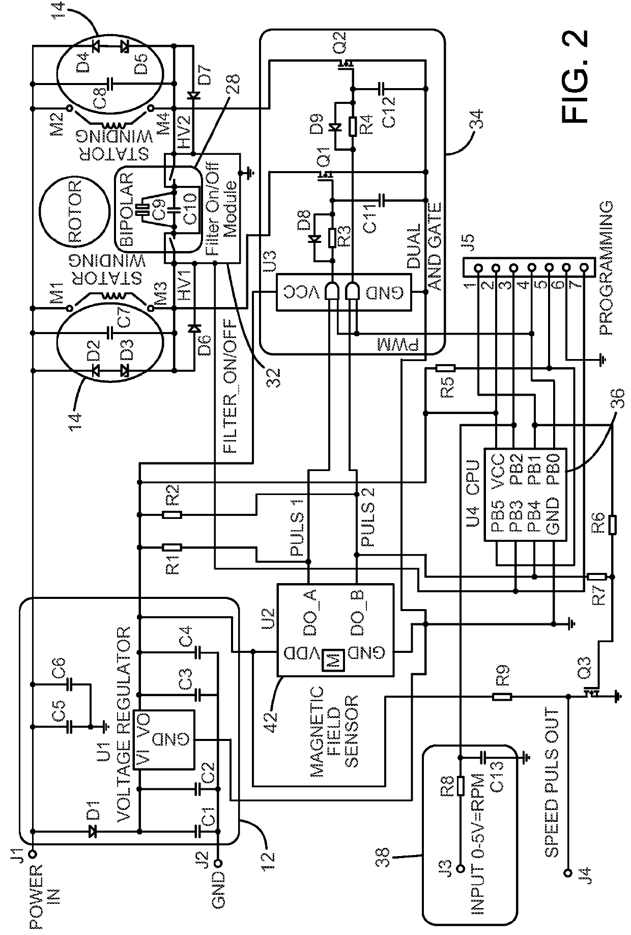
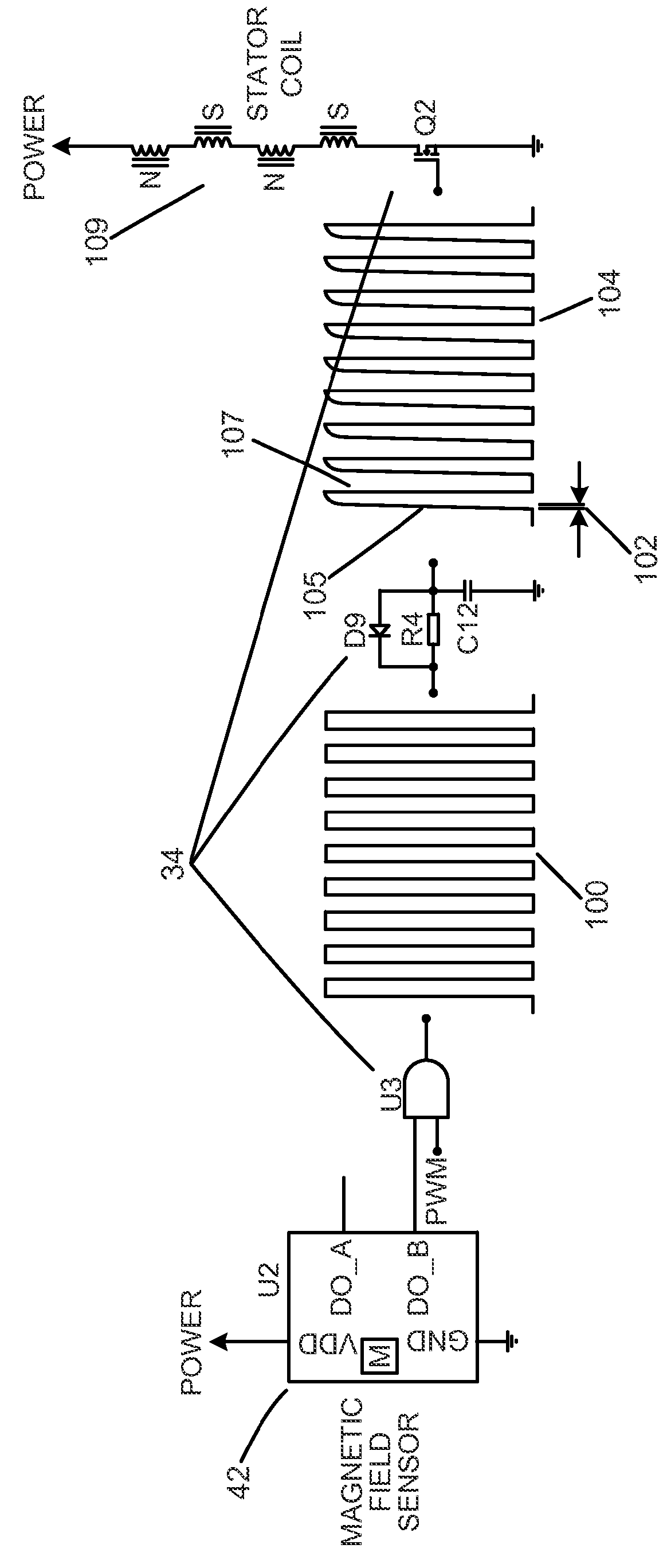
[0030]The present invention relates to a brushless DC motor made up of a stator with a number of windings which are magnetized by a current flowing through the different windings. It is to be understood that the invention is not limited to brushless DC motors and that any suitable type of motor may be used. The brushless DC motor is merely used as an illustrative example. The current at least partially depends on the windings number of turns, the area of the wire, and the applied PWM signal. Preferably, the stator windings should be wound so that the required power can be obtained with the high PWM frequency. Because the inductance opposes fast current changes, the windings should have a sufficiently low inductance so that desired current level can be reached. In other words, the stator should be wound in such a way that the desired or required current that is to be drawn through the windings can be accomplished at the PWM frequency used. If the inductance is too high, it is not pos...


PUM


Abstract

The method is for making a brushless direct-current (DC) motor quieter. A predetermined high frequency pulse width modulated (PWM) signal is generated. The PWM signal is sent to a first filter. The first filter truncates the PWM signal to provide the PWM signal with a rise time. The rise time allows transistors connected thereto to open smoothly. A second filter is provided that has a non-polarized capacitor. In a coil switching process, the non-polarized capacitor operates as a voltage or current absorption circuit between driving transistors. The coil switching process creates transient energy of voltage transients. The non-polarized capacitor absorbs the transient energy.

Description

TECHNICAL FIELD[0001]The present invention pertains to a method for making a motor quieter such as a brushless direct current motor.BACKGROUND AND SUMMARY OF INVENTION[0002]Brushless fans are utilized in for instance computers, desktop fans, bathroom fans, and ventilation fans, and the like, because they are not as noisy as those operated by brushes. Nevertheless, brushless fan motors when operated, and when the stator energized electro-magnetic coils change polarization, an unwanted clicking or snapping noise can be heard particularly when the revolving fan blades do not override the clicking noise made by the fan motor. It is sometimes important that ventilation fans are as quiet as possible and the clicking noise should therefore be suppressed to avoid the noise problem.[0003]A brushless fan motor can be driven by direct current (DC) by feeding DC to driver transistors through which the coils are energized. One object of the present invention is to provide a brushless DC motor, w...

Claims


Application Information

Patent Timeline
Patent Type & Authority Patents(United States)
IPC IPC(8): G05B11/28H02P6/08
CPCH02P6/08F04D29/663
Inventor DERNEBO, LARS
Owner LD DESIGN ELECTRONICS
Why Eureka
Try Eureka