
Sub-carrier successive approximation millimeter wave radar for high-accuracy 3D imaging

a millimeter wave radar and high-accuracy technology, applied in the field of sub-carrier successive approximation millimeter wave radar for high-accuracy 3d imaging, can solve the problems of limited accuracy, limited use of phase-based radar, intrinsic range ambiguity, etc., and achieve the effect of reducing the cost of operation and increasing the accuracy of the radar

Active Publication Date: 2016-05-17
RGT UNIV OF CALIFORNIA
View PDF9 Cites 1 Cited by
  • Summary
  • Abstract
  • Description
  • Claims
  • Application Information

AI Technical Summary

Benefits of technology

[0013]Instead of utilizing FMCW, the present invention is a phase-based radar which directly measures the round trip time by estimating the phase delay of the carrier. One of its unique advantages is that the frequency of the carrier does not need to be swept as in conventional radars, thereby relaxing RF front-end bandwidth and linearity requirements. Any level of desired accuracy may be achieved using the SCSA radar, with accuracy being limited only by the extent of system noise. In general, the accuracy is determined by the number of successive approximations performed, and the period over which the output radar signal is integrated. For example, providing that the target is a slow motion object, such as less than 10 meters per second (m / s), which is common for security screening, an integration time of 1 μs results in only 0.01 mm of distance inaccuracy and 0.008 mm of inaccuracy associated with the Doppler shift.
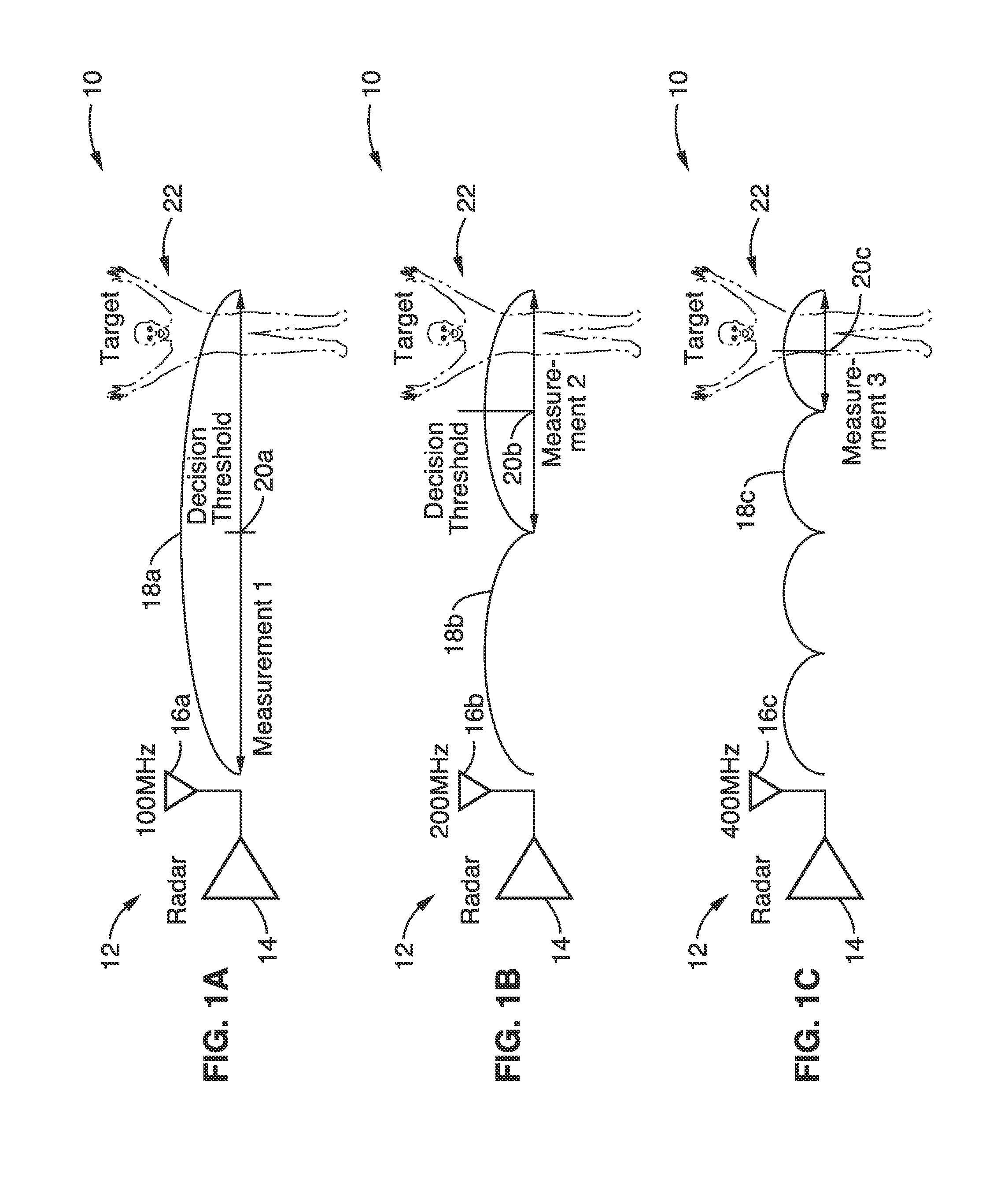
[0017]In addition, in at least one embodiment of the invention, the IF signal is configured for operation at several frequencies to successively approximate the target distance. By using multiple frequencies that are related by powers of two (i.e., 100 MHz, 200 MHz, 400 MHz . . . and so forth), the ambiguity associated with conventional phase based radar can be alleviated and extremely high accuracy can be achieved.
[0019]The present invention provides a number of advantages, of which the following are listed by example and not limitation. (1) SCSA radar provides high accuracy which is higher than that provided by FMCW or other radar techniques by at least ten fold (10×) due to the high operating frequencies. (2) SCSA phase based radar benefits from relaxed radio requirements, as it is narrowband with far more relaxed requirements on the transmitter and receiver than possible using wideband FMCW or pulsed-radar systems. (3) SCSA radar provides potentially unlimited accuracy. Unlike FMCW radar, where a carrier frequency sweeping is required, the accuracy of SCSA is limited only by signal noise, so increasing number of measurement iterations and integration time allows radar accuracy to be increased.
[0020]A prototype of the SCSA radar has been constructed using a 65 nm CMOS process, and successfully demonstrated at 144 GHz with better than 1 cm of accuracy at a one meter target distance. It appears that SCSA radar offers the highest achievable accuracy in radar systems to date. Applications for this system are widespread from security screening to aerospace and automotive navigation. The successive approximation method used herein can be readily implemented on existing carrier wave radar hardware, simplifying manufacture.

Problems solved by technology

Any level of desired accuracy may be achieved using the SCSA radar, with accuracy being limited only by the extent of system noise.
One issue, however, which limits the use of phase-based radar, is its intrinsic range ambiguity as the target travels beyond one wavelength of the carrier.
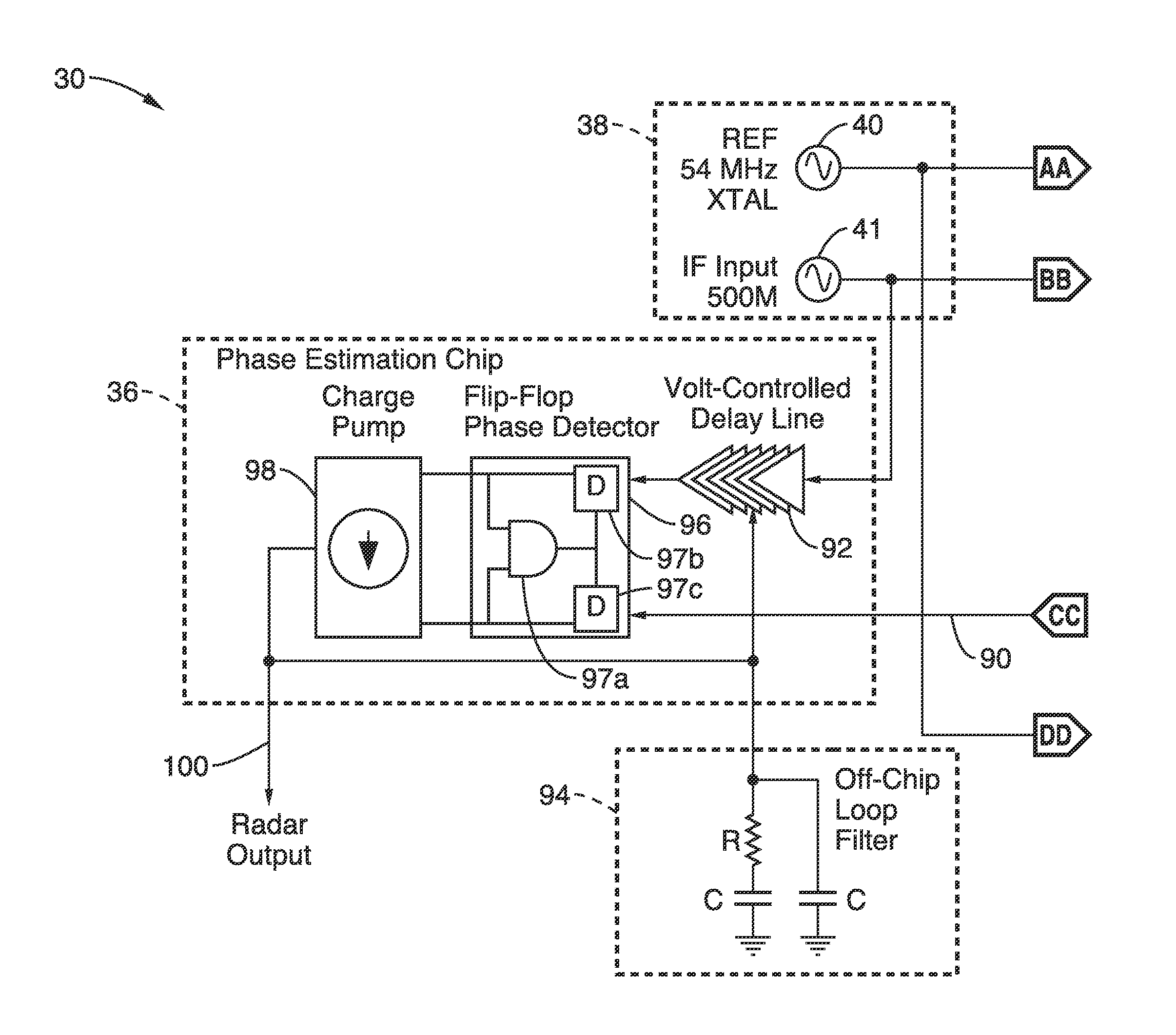
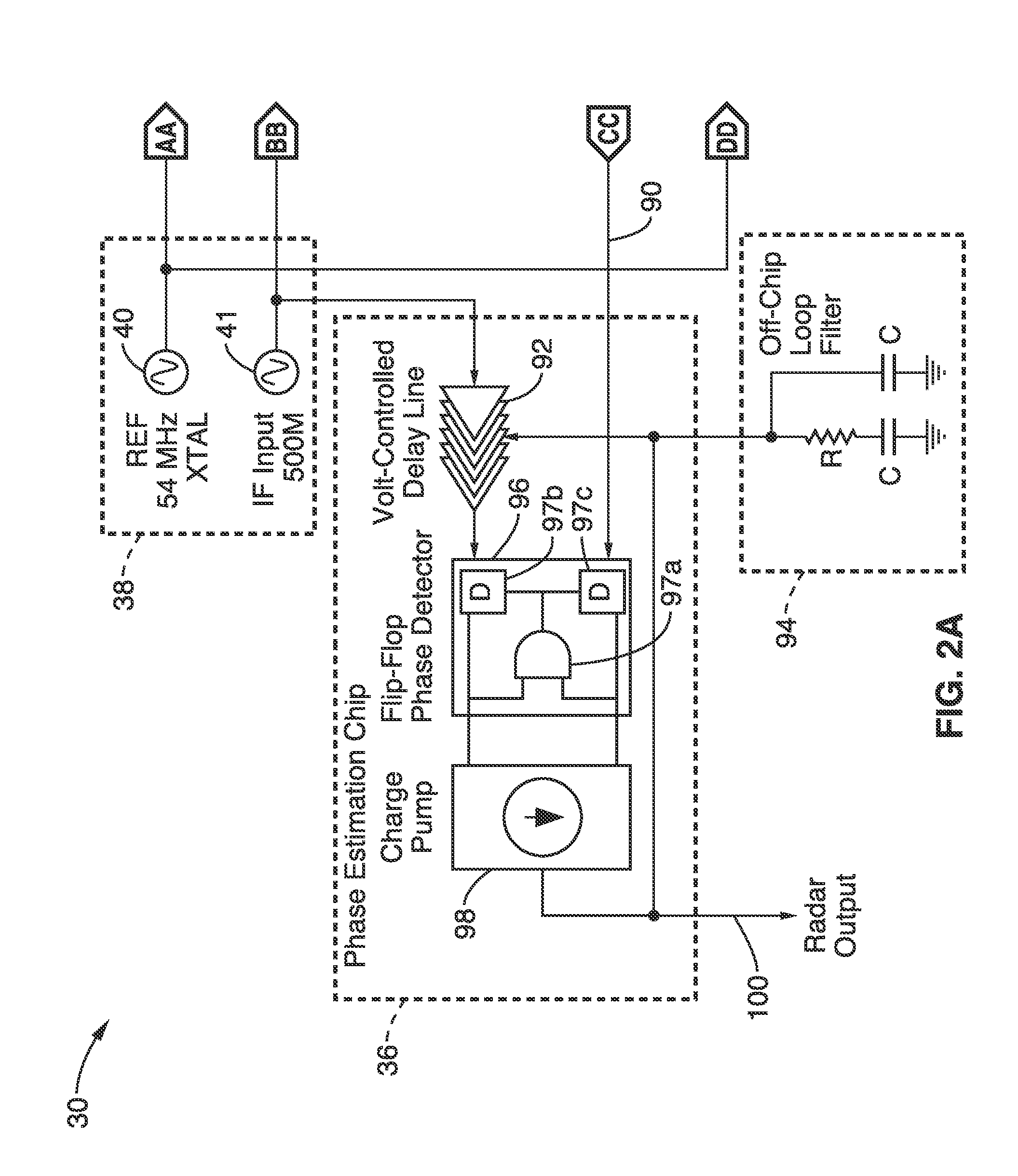
As directly resolving the carrier phase at the intended frequency is quite difficult, the inventive embodiments conduct successive ranging measurements at increasing intermediate frequencies (IF) for range detection without distance ambiguity.

Method used


Image

  • Sub-carrier successive approximation millimeter wave radar for high-accuracy 3D imaging
  • Sub-carrier successive approximation millimeter wave radar for high-accuracy 3D imaging
  • Sub-carrier successive approximation millimeter wave radar for high-accuracy 3D imaging

Examples


Embodiment Construction

[0030]FIG. 1A through FIG. 1C show an embodiment 10 exemplifying the basic detection principle of the successive approximation sub-carrier radar. A radar system 12 is shown with transmitter and receiver (Tx / Rx) 14 and multiple intermediate (sub-carrier) frequencies, for example 100 MHz 16a in FIG. 1A, 200 MHz 16b in FIG. 1B, and 400 MHz 16c in FIG. 1C. A first measurement is seen with IF at 100 MHz with waveform 18a shown directed at target object (individual) 22. It can be seen in FIG. 1A that based on the decision threshold 20a, seen at mid-waveform, the target is more than a half wavelength away. The IF is increased (e.g., doubled) with waveform 18b, as seen in FIG. 1B, wherein the target is seen in the last half of the second waveform, based on the decision threshold 20b. IF is increased again in FIG. 1C with waveform 18c, with the target showing up near the center of the fourth waveform, with decision threshold 20c. A decision threshold is seen with each waveform, wherein depen...


PUM


Abstract

A sub-carrier successive approximation (SCSA) radar having a sufficiently high accuracy to capture 3D images of concealed objects. The invention is phase-based, and directly measures round trip time by estimating the phase delay of the carrier. One of its advantages is that the carrier does not need to sweep across a wide frequency range, thereby relaxing RF front-end bandwidth and linearity requirements. SCSA radar accuracy is limited only by the extent of system noise, allowing very high accuracy to be achieved with a sufficient integration period. The SCSA radar can be readily implemented in CMOS, as well as other device technologies, and fabricated within one or more small integrated circuits.

Description

CROSS-REFERENCE TO RELATED APPLICATIONS[0001]This application is a 35 U.S.C. §111(a) continuation of PCT international application number PCT / US2013 / 023319 filed on Jan. 25, 2013, incorporated herein by reference in its entirety, which claims priority to, and the benefit of, U.S. provisional patent application Ser. No. 61 / 591,349 filed on Jan. 27, 2012, incorporated herein by reference in its entirety. Priority is claimed to each of the foregoing applications.[0002]The above-referenced PCT international application was published as PCT International Publication No. WO 2013 / 112955 on Aug. 1, 2013, which publication is incorporated herein by reference in its entirety.STATEMENT REGARDING FEDERALLY SPONSORED RESEARCH OR DEVELOPMENT[0003]Not ApplicableINCORPORATION-BY-REFERENCE OF COMPUTER PROGRAM APPENDIX[0004]Not ApplicableNOTICE OF MATERIAL SUBJECT TO COPYRIGHT PROTECTION[0005]A portion of the material in this patent document is subject to copyright protection under the copyright laws...

Claims


Application Information

Patent Timeline
Patent Type & Authority Patents(United States)
IPC IPC(8): G01S13/38G01S13/90G01S7/03G01S7/20G01S13/88G01S13/34
CPCG01S7/032G01S13/90G01S7/20G01S13/38G01S13/347G01S13/887
Inventor CHANG, MAU-CHUNG FRANKTANG, ADRIAN J.
Owner RGT UNIV OF CALIFORNIA
Learn More