
Modular electronic detection device

a detection device and module technology, applied in the field of electronic devices, can solve the problems of increasing the weight of the cable, affecting the aerodynamics, and affecting the flight safety of the aircraft, so as to reduce the amount of cables, shorten the installation time, and reduce the mass on board

Active Publication Date: 2016-05-03
EURON AERONAUTIC DEFENCE & SPACE
View PDF6 Cites 8 Cited by
  • Summary
  • Abstract
  • Description
  • Claims
  • Application Information

AI Technical Summary

Benefits of technology

This solution reduces the number of cables, minimizes mass and space, shortens installation and maintenance times, and allows for dynamic reconfiguration of aircraft systems, enhancing reliability and flexibility.

Problems solved by technology

Installing electronic systems in aircraft is very time-consuming.
The amount of cables makes for high mass, which has an impact on the performance of the aircraft.
This imposes major constraints in terms of space allocation, to the point that if all these cables are to be installed, the aerodynamics may be changed.
However, even in recent airplanes or those still being developed, the critical signals are not multiplexed, because of the level of reliability required.
Finally, current solutions to the problem do not permit easy reconfiguration, because of the quantity of cables to be modified and because of the coupling of mechanical control and electrical commutation.

Method used


Image

  • Modular electronic detection device
  • Modular electronic detection device
  • Modular electronic detection device

Examples


Embodiment Construction

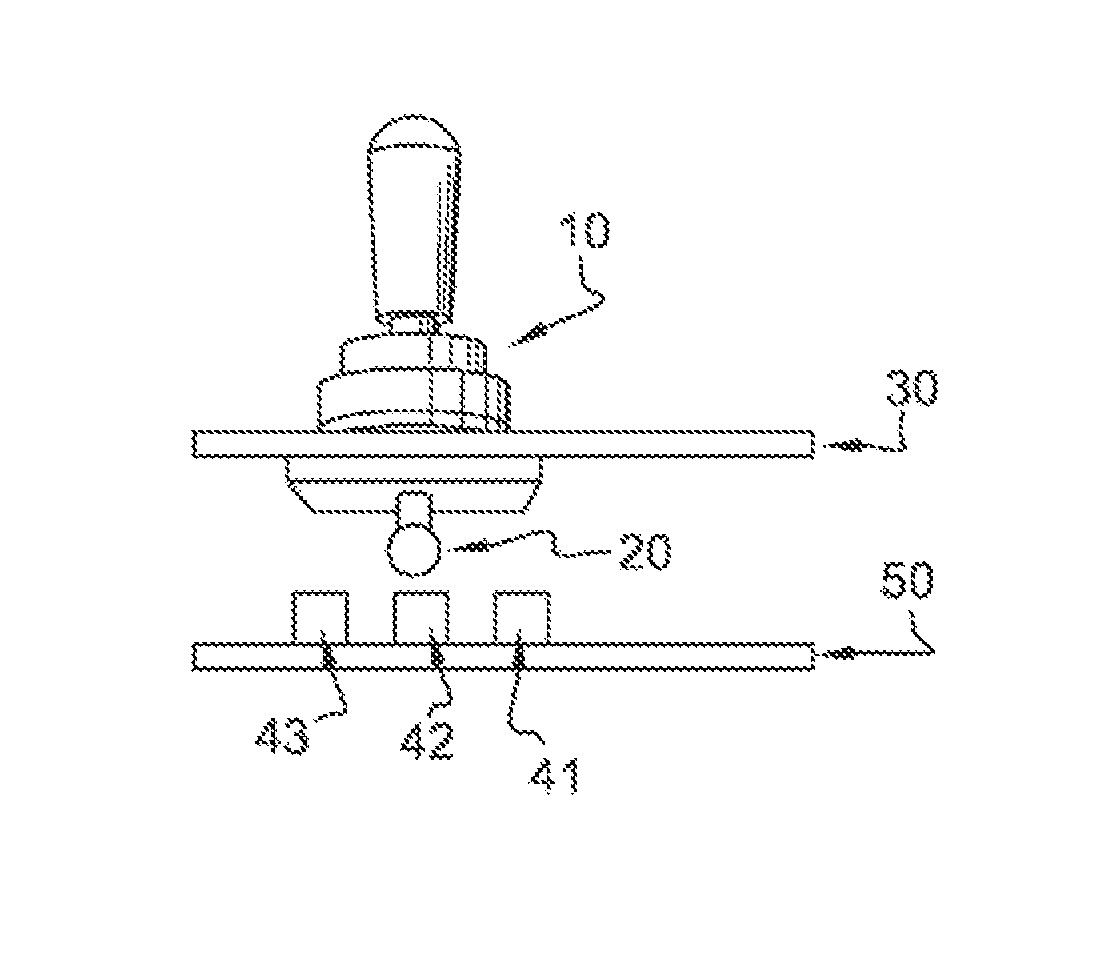
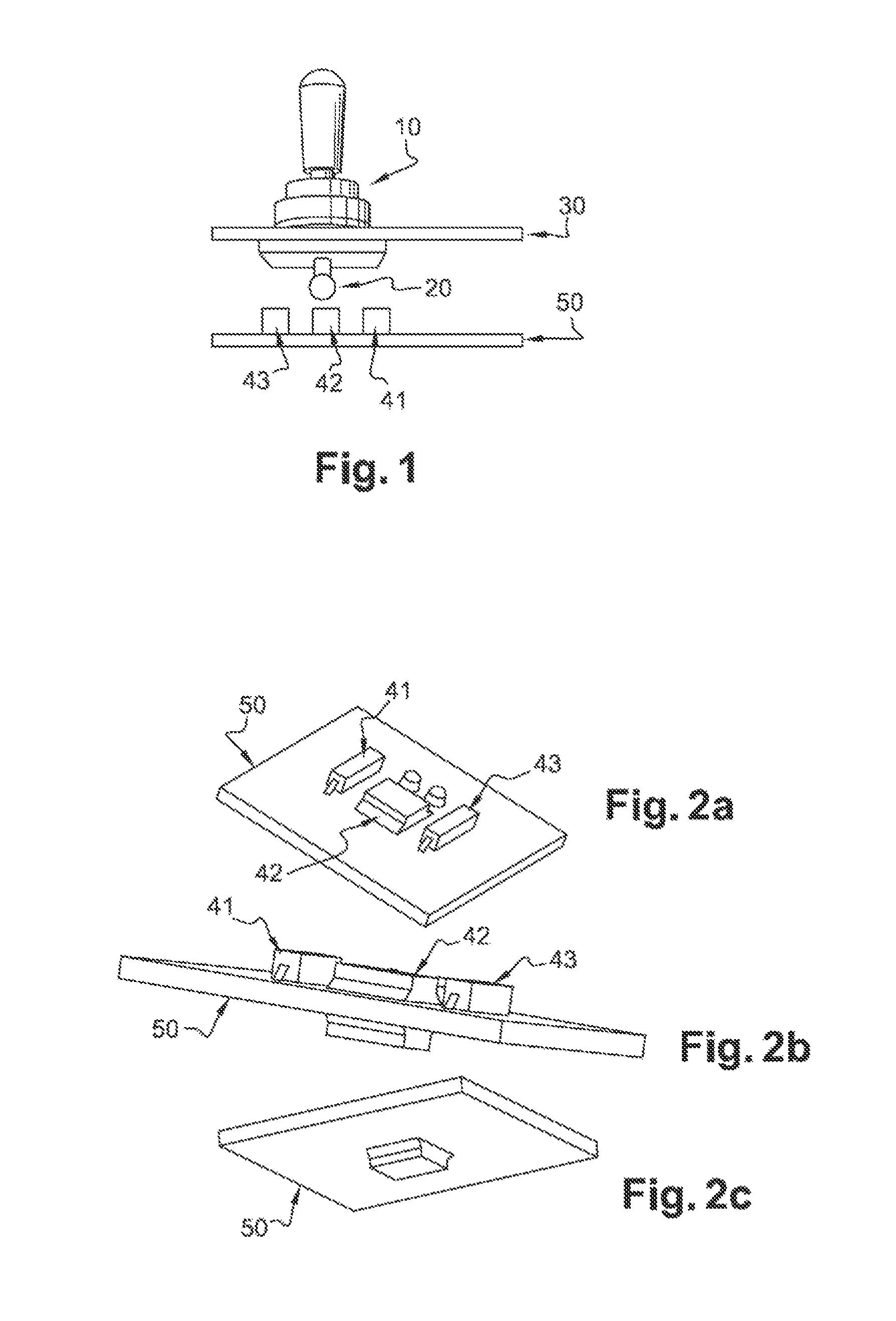
[0043]FIG. 1 is a basic diagram of the device according to the present invention.

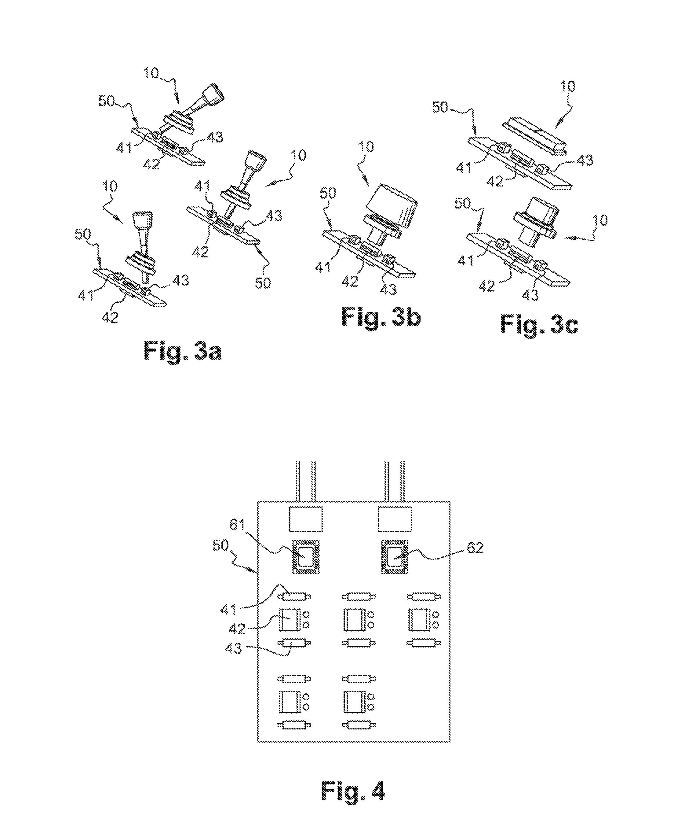
[0044]The modular, generic electronic detection device, shown in FIG. 1, comprises: a mechanical actuator 10 linked to a target 20 through a front face of a panel 30; and a plurality of position sensors 41, 42, 43 of the target 20 linked to a printed circuit board 50.

[0045]The principle thus proposed makes it possible, by a single modular electronic device, to physically decouple mechanical control and detection / information analysis; and detection and analysis of information from various types of mechanical actuators (pushbutton, rotary button, two- or three-position switch button, etc.).

[0046]The sensors can be installed on either side of a rigid, flexible, or flexible / rigid support for a printed circuit in a uniform manner (one mold per support) or combined manner (a plurality of molds per support.

[0047]Because of its size, this electronic device is easily integrated on a minimal surface area, which i...


PUM


Abstract

A modular electronic detection device comprises a mechanical actuator connected to a target through a front surface of a panel. The device further comprises a plurality of sensors for detecting the position of the target, which are connected to a printed circuit board. The modular detection device of the present invention can be incorporated into an aircraft and can be used in aircraft assembly.

Description

RELATED APPLICATIONS[0001]This application is a §371 application from PCT / EP2012 / 056929 filed Apr. 16, 2012, which claims priority from French Patent Application No. 11 53555 filed Apr. 26, 2011, each of which is herein incorporated by reference in its entirety.FIELD OF THE INVENTION[0002]The present invention relates to the field of electronics. More particularly, the present invention relates to a modular electronic detection device.STATE OF THE ART[0003]Installing electronic systems in aircraft is very time-consuming. Furthermore, such operations are part of the critical path of aircraft assembly.[0004]The amount of cables makes for high mass, which has an impact on the performance of the aircraft.[0005]Furthermore, expanding electrical systems locally increase the density of cables, especially in the cockpit zone and in the electronics area of the aircraft. This imposes major constraints in terms of space allocation, to the point that if all these cables are to be installed, the...

Claims


Application Information

Patent Timeline
Patent Type & Authority Patents(United States)
IPC IPC(8): H03K17/51H01H36/00H01H23/28H01H23/24H01H19/08H01H13/10
CPCH03K17/51H01H36/006H01H13/10H01H19/08H01H23/24H01H23/28
Inventor MOREAU, KATELLDANTIN, BENOITCHEVASSUS, NICOLAS
Owner EURON AERONAUTIC DEFENCE & SPACE
Learn More