
Preform clamping head

a technology of clamping head and clamping head, which is applied in the direction of manufacturing tools, metal-working machine components, positioning apparatuses, etc., can solve the problems of leakage and scrapping of products, cumbersome processing operations, and high cost, and achieves stable rotation, simple manufacturing process, and easy installation

Inactive Publication Date: 2016-05-03
GUANGZHOU TECH LONG PACKAGING MACHINERY CO LTD
View PDF25 Cites 0 Cited by
  • Summary
  • Abstract
  • Description
  • Claims
  • Application Information

AI Technical Summary

Benefits of technology

[0007]The purpose of this invention is to provide a preform clamping head, which is full of stable rotation and easy installation with simple manufacture process and low manufacture cost. The further purpose of it is to significantly reduce the probability of abrasion of the bottle mouth.
[0009]The annular sleeve body described in this invention is made of engineering plastic. The preform clamping head of the present invention is equipped with an annular sleeve body, whose outer surface inclines outwardly from bottom to top. The preform clamping head driven by the heating chain may insert downward into the bottle mouth, and press the upper part of the annular sleeve body simultaneously to make it retract inward, allowing the preform clamping head to go downward further. When the heating chain stops going down, the outer surface of the upper part of the annular sleeve body and the bottle mouth will press against each other, making the annular sleeve body stick to the inner surface of the bottle mouth. Since the integral structure of the annular sleeve body, this invention has very simple manufacture process and low manufacture cost compared with that of the existing technology in which corresponding parts are processed separately and then assembled together. Especially, by means of the integral molding mode, the axial requirement of the preform clamping head is easier to be satisfied, so that the bottle preform clamped on the outer surface of the sleeve body is capable of rotating stably along the heating chain and can be heated more uniformly during the heating process. In addition, the annular sleeve body adopts engineering materials, so its surface is smooth and its hardness is similar to the bottle preform, so the probability of abrasion of the bottle mouth can be reduced significantly.

Problems solved by technology

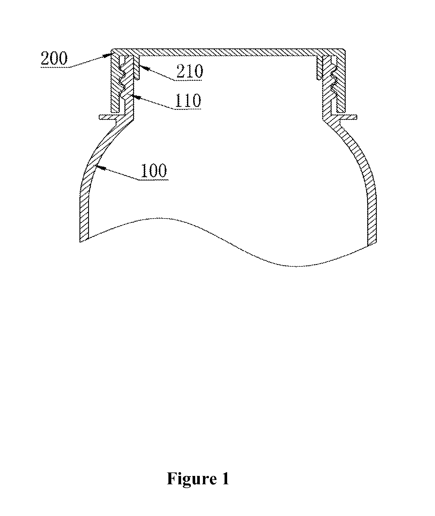
Therefore, no gap (for example, that due to abrasions of the bottle inner wall) is allowed at the location where the outer surface of sealing ring 210 and the inner wall of the bottle mouth 110 against each other, or the seal of the lightweight bottle will be harmed, resulting in leakage and scrapped product.
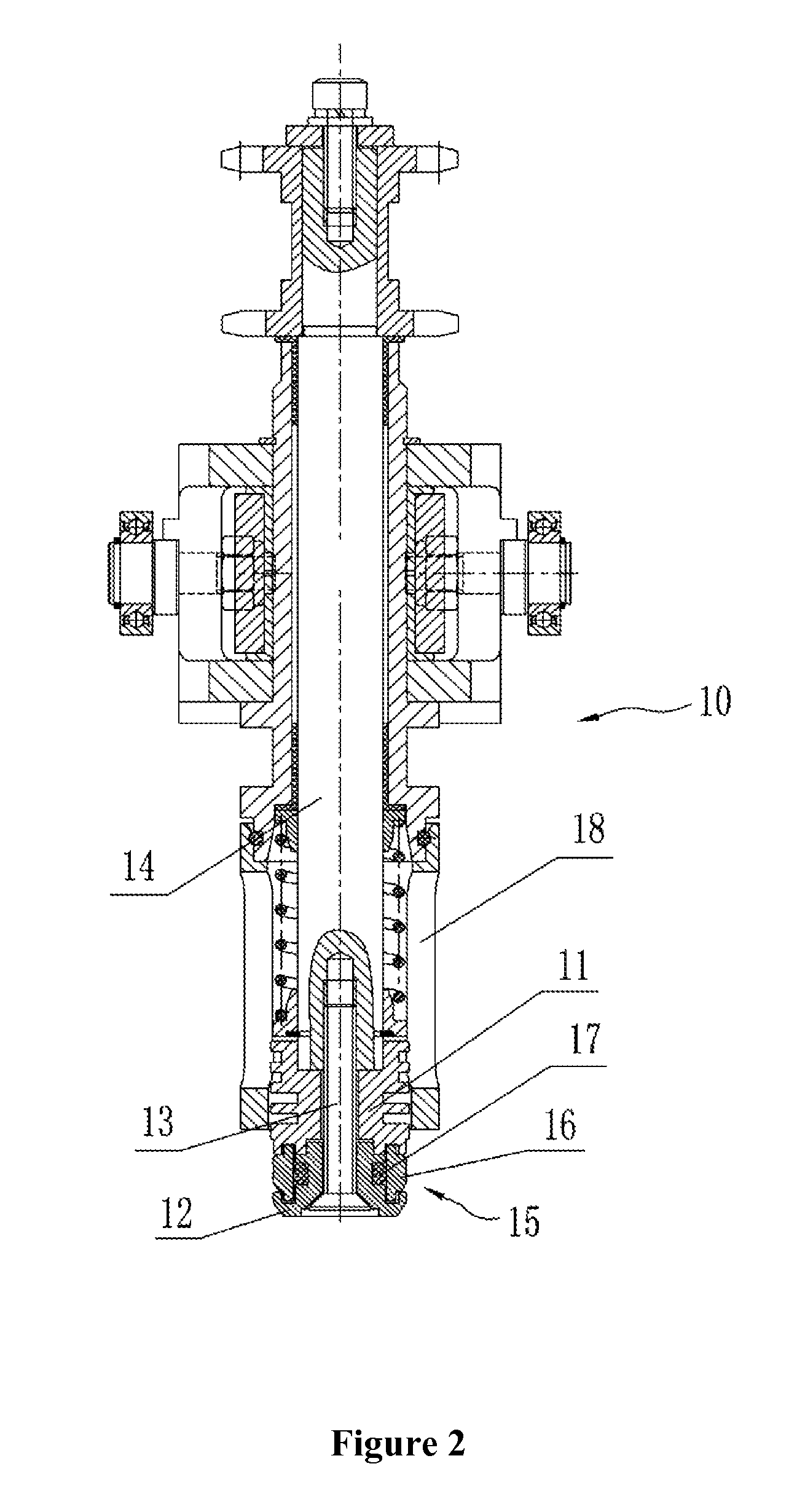
However, there are some shortcomings in the preform clamping head under the existing technology: 1. The preform clamping head is assembled from multiple parts, which have to be processed separately, leading to cumbersome processing operations and high cost; 2. The matching accuracy of parts processed separately is difficult to control.
The stainless steel expanding plate 16 after assembling is hard to be uniformly distributed around the axis of rotation of the heating chain 10, resulting in deviation of axis of the bottle preform stuck outside the stainless steel expanding plate 16 from the rotation axis of heating chain 10, leading to uneven heating of the bottle preform due to the shaking and thereby harming the quality of blow molding; 3. When assembling the preform clamping head to the sleeve shaft 14, it is necessary to join the insert head 11 to the heating head 12 and attach all stainless steel expanding plate 16 to it firstly and it is quite troublesome indeed; and 4.

Method used


Image

  • Preform clamping head
  • Preform clamping head
  • Preform clamping head

Examples


Embodiment Construction

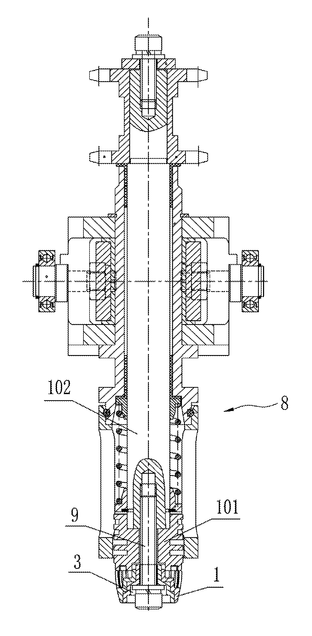
[0015]As shown in FIGS. 2 to 5, the preform clamping head of the invention is installed in the lower part of a heating chain 8. It includes an integral annular sleeve body 1, the outer surface of which inclines outwardly from bottom to top in the shape an arc or a straight line, and the upper part of which is provided with a retracting space 2 for the inward retracting of the annular sleeve body 1 when it is pressed. The preform clamping head driven by the heating chain 8 may insert downward into the bottle mouth, and press the upper part of the annular sleeve body 1 simultaneously to make it retract inward, allowing the preform clamping head to go downward further. When the heating chain 8 stops going down, the outer surface of the upper part of the annular sleeve body 1 and the bottle mouth will press against each other, making the annular sleeve body 1 stick to the inner surface of the bottle mouth. Due to the integral structure of the annular sleeve body 1, this invention has ve...


PUM

PropertyMeasurementUnit
strengthaaaaaaaaaa
shapeaaaaaaaaaa
outer diameteraaaaaaaaaa

Abstract

A preform clamping head which is mounted at the lower part of a heating chain (8) includes an integral annular sleeve body (1), the outer surface of which inclines outwardly from bottom to top and the upper part of which is provided with a retracting space (2) for the inward retracting of the annular sleeve body when it is pressed. The invention has simple manufacture process and low manufacture cost. By means of the integral molding mode, the axial requirement of the preform clamping head is easier to satisfy, so that the bottle preform clamped on the outer surface of the sleeve body is capable of rotating stably along the heating chain and can be heated more uniformly during the heating process.

Description

[0001]The present application is a 371 of International application PCT / CN2011 / 000551, filed Mar. 3, 2011, which claims priority of CN 201110031050.2, filed Jan. 28, 2011, the priority of these applications is hereby claimed and these applications are incorporated herein by reference.TECHNICAL FIELD[0002]This invention relates to a preform clamping head, especially which used in the blowing-filling-capping combi-block (BFC combi-block) for clamping the bottle preform.BACKGROUND OF THE INVENTION[0003]In order to save material and respond to the call of the national energy saving, the beverage industry has launched “lightweight packaging”, utilizing lightweight bottles to package carbonated soft drinks and purified water and other drinking water, as the lightweight bottle shown in FIG. 1. It includes the bottle body 100 and the cap 200 connected together with screw thread. Cap 200 is provided with a downward seal ring 210, whose outer diameter on the upper part is slightly larger than...

Claims


Application Information

Patent Timeline
Patent Type & Authority Patents(United States)
IPC IPC(8): B23Q3/00B29C49/42
CPCB23Q3/00B29C49/4205
Inventor ZHANG, JIESHENG
Owner GUANGZHOU TECH LONG PACKAGING MACHINERY CO LTD
Learn More