Vibration device, article conveyance device, and article sorting device

a technology of article conveyance and vibration device, which is applied in the direction of mechanical vibration separation, solid separation, grading, etc., can solve the problems of easy cause of equipment problems, complex control scheme, and high manufacturing cost and maintenance expenses, so as to reduce the height up to the conveyance surface, reduce the height, and facilitate the effect of elastic suppor

Active Publication Date: 2016-04-19
SINFONIA TECHNOLOGY CO LTD
View PDF10 Cites 4 Cited by
  • Summary
  • Abstract
  • Description
  • Claims
  • Application Information

AI Technical Summary

Benefits of technology

The first invention provides a vibration device that can support a movable bench in three directions independently while reducing in size. This device can also reduce the height of the conveyance surface and prevent the movable bench from pitching and rolling. Additionally, the second invention provides a vibration device that can stabilize the base and further improve the operation accuracy of the movable bench, while also preventing vibrations from propagating to the installation surface and creating a better work environment. Both invention's vibration devices are excellent for use in article conveyance and sorting devices.

Problems solved by technology

The article conveyance devices according to the conventional technologies of the Patent Literatures 1 to 3 are configured from a large number of equipments such as the electrostatic actuator and the small roller, and need to drive the equipments simultaneously, thereby the configuration becomes complex and a control scheme become also complex.
Therefore, manufacturing costs and maintenance expenses become higher, and furthermore problems with the equipment are also easily caused.
Also, in such configurations, since concavities and convexities are caused at the conveyance surface with which the article comes into contact, it becomes difficult to convey the article as the article becomes smaller with respect to the concavities and convexities.
Thus, it is difficult to enable conveyance of articles having varying sizes from small to large by using a single article conveyance device.

Method used


Image

  • Vibration device, article conveyance device, and article sorting device
  • Vibration device, article conveyance device, and article sorting device
  • Vibration device, article conveyance device, and article sorting device

Examples


first embodiment

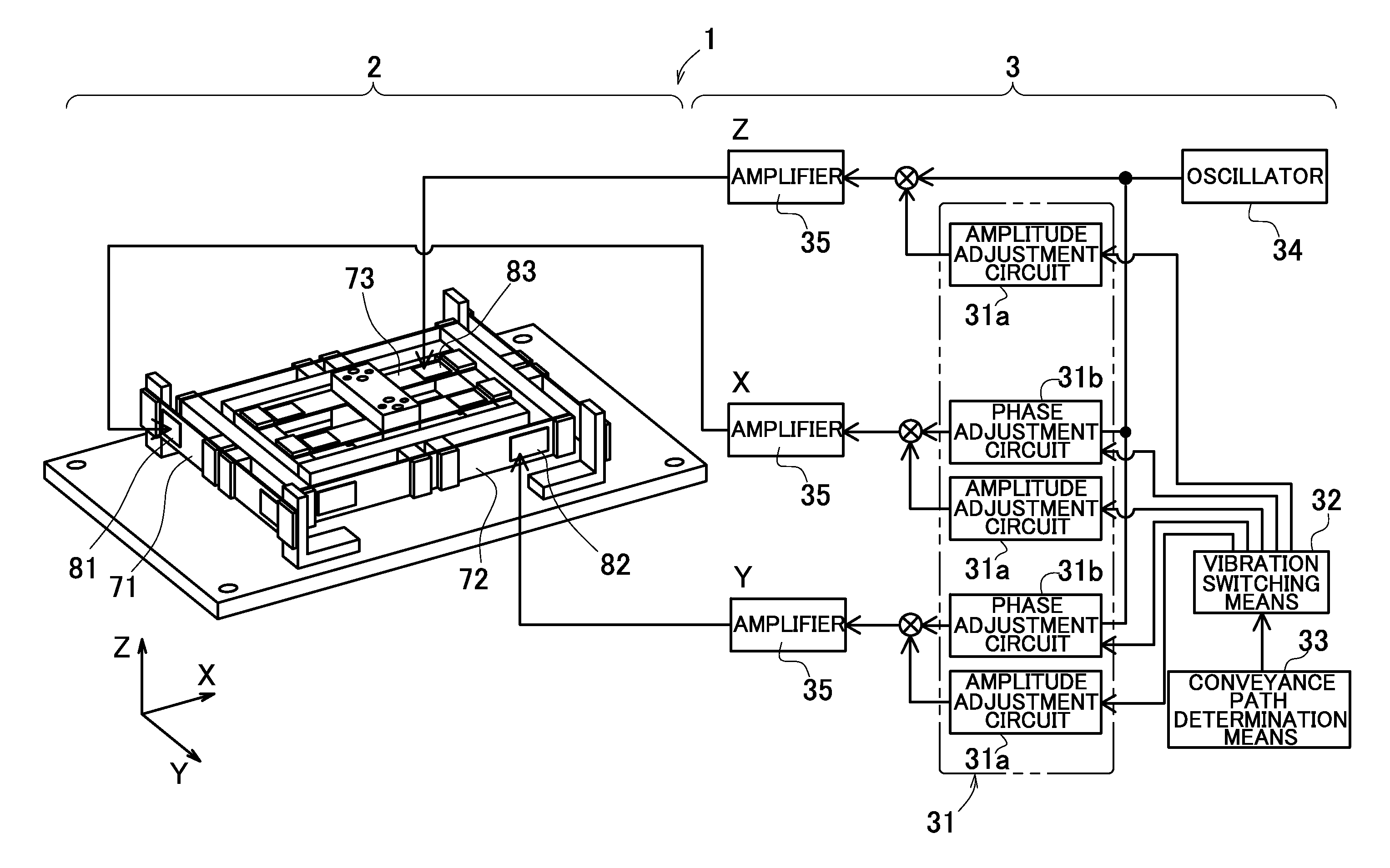
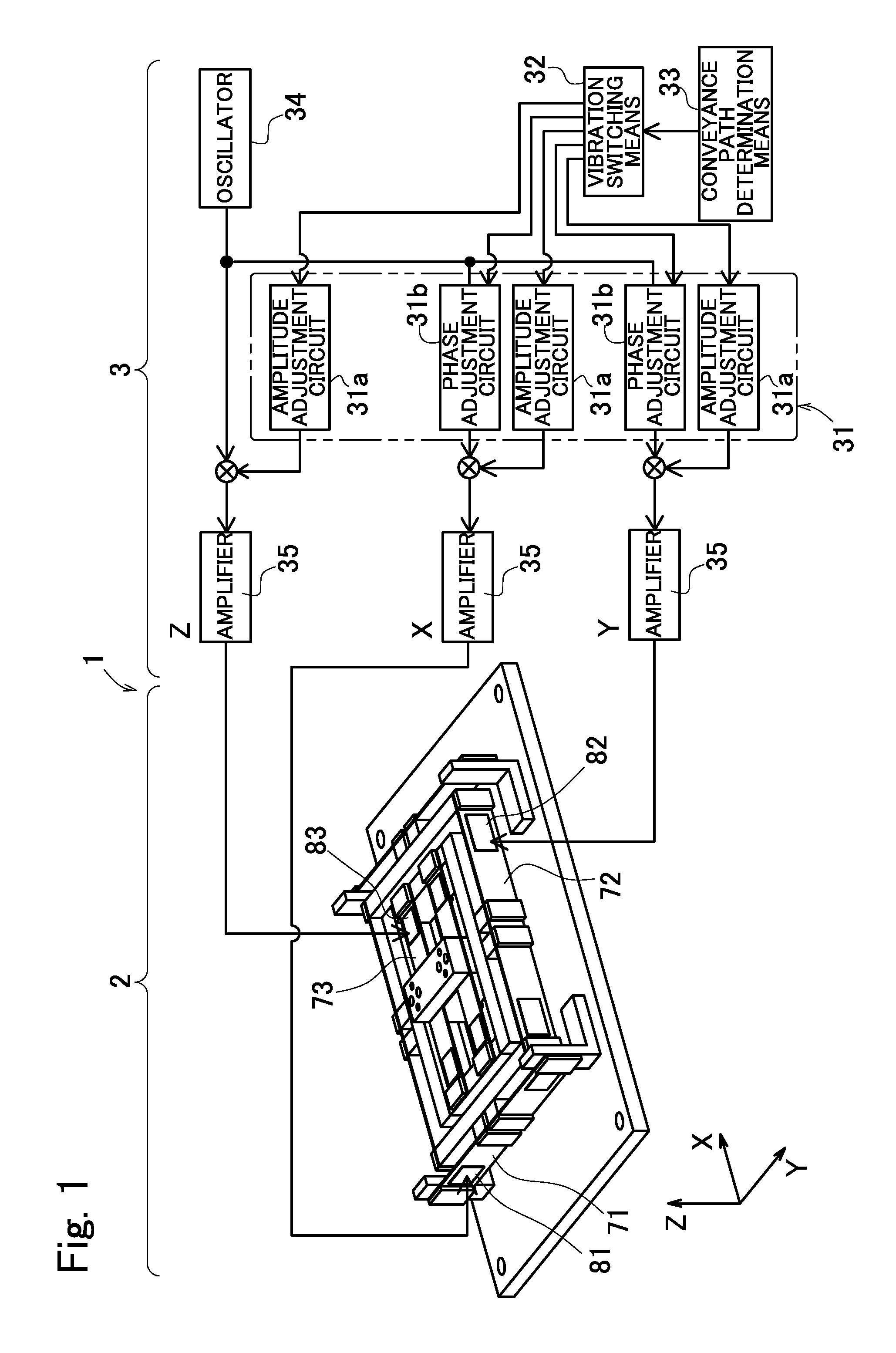
[0082]In FIG. 1, a form in which a vibration device 2 according to the present invention and in addition a control system unit 3 for controlling the vibration device 2 are configured as an article conveyance device 1 that is one of article moving devices, is illustrated.

[0083]The control system unit 3 is configured such that, by performing control of piezoelectric elements 81, 82, and 83 incorporated in the vibration device 2 as described later, periodic excitation forces in each direction, that is, in X as a first horizontal direction, Y as a second horizontal direction, and Z as a vertical direction are imparted to the vibration device 2 to cause vibrations.

[0084]Note that, each direction of the X, Y, and Z is defined as indicated in the coordinate axis illustrated in the drawings, and also in the following the explanation will be advanced along the coordinate axis illustrated in the drawings as appropriate.

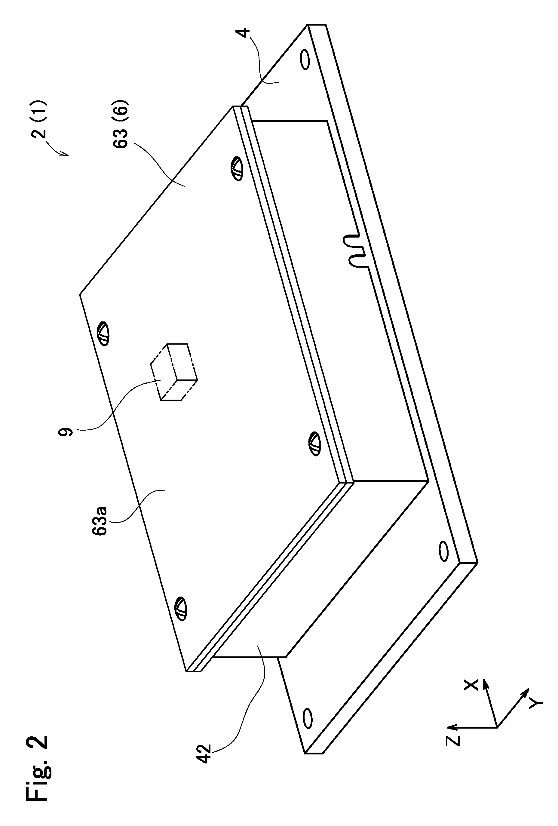
[0085]FIG. 2 illustrates the above-described vibration device 2 as a state...

fourth embodiment

[0188]In FIG. 22, a form in which a vibration device 302 according to the present invention and in addition the control system unit 3 for controlling this device 302 are configured as an article conveyance device 301 that is one of the article moving devices, is illustrated.

[0189]The vibration device 302 illustrated in this figure is in a state where a mounting bench and a peripheral wall part which are described later are removed, and a state where a drive part 325 is exposed, and the drive part 325 is elastically supported on a base 304, and piezoelectric elements 381, 382, and 383 as the excitation means are provided in the drive part. In addition, the base 304 is elastically supported on a fixed bench 321.

[0190]The control system unit 3 is configured such that the vibrations are caused by performing a control of the voltage to be applied to the piezoelectric elements 381, 382, and 383 to impart the periodic excitation force to the vibration device 302 in each direction of the X ...

second embodiment

[0259]Therefore, the same action as explained using FIG. 16 to FIG. 20 in the second embodiment can be caused, and similar to this, the sorting of articles 9 can be performed preferably.

[0260]As described above, in the present embodiment, since the same device as the vibration device 302 explained in the fourth embodiment is used, the same effect as the vibration device 302 explained in the above-described fourth embodiment can be obtained.

[0261]In addition to that, the article sorting device 401 as the article moving device according to the present embodiment comprises the above-described vibration device 302, and the vibration control means 31 that controls the piezoelectric elements 381 to 383 so as to cause three-dimensional vibration trajectory to the movable bench 306 by simultaneously generating the periodic excitation forces by the piezoelectric elements 381 to 383 as the plurality of excitation means which the vibration device 302 has, with the phase difference and at the s...


PUM


Abstract

A vibration device includes a base, a movable bench elastically supported with respect to the base, a first horizontal excitation unit that vibrates the movable bench in a first horizontal direction, a second horizontal excitation unit that vibrates the movable bench in a second horizontal direction that crosses the first horizontal direction, a vertical excitation unit that vibrates the movable bench in a vertical direction, and first and second middle benches between the base and the movable bench, wherein first to third plate-like spring members elastically connect the base, the first and second middle benches, and the movable bench sequentially in the first horizontal direction, the second horizontal direction, and the vertical direction.

Description

TECHNICAL FIELD[0001]The present invention relates to an article conveyance device that conveys an article on a movable bench by vibration of the movable bench, an article sorting device that sorts a plurality of articles on the movable bench, and a vibration device applicable to the article conveyance device and the article sorting device.BACKGROUND ART[0002]Conventionally, as an article conveyance device that can convey an article and can arbitrarily change a conveyance direction on a conveyance line of the article, a various types of devices are known.[0003]For example, as Patent Literature 1, there is a type of article conveyance device in which a large number of electrostatic actuators are disposed in a lattice shape on a conveyance surface of an article. In this device, the article is moved on a carrier, by providing a large number of square-shaped stators on the conveyance surface, and suspending the carrier therein via a spring member in advance, and by operating an attracti...

Claims


Application Information

Patent Timeline
Patent Type & Authority Patents(United States)
IPC IPC(8): B65G27/18B06B1/06B07B13/11B65G27/24B65G27/32B65G47/26B65G27/26
CPCB65G27/18B06B1/0603B07B13/113B65G27/26B65G27/32Y10T74/18856B65G27/24B65G2812/0308
Inventor KIMURA, TETSUYUKIMURAGISHI, YASUSHI
Owner SINFONIA TECHNOLOGY CO LTD
Why Eureka
Try Eureka