Polishing pad

a technology of polishing pad and surface, which is applied in the field of polishing pad, can solve the problems of difficult to suppress and achieve the effect of effectively suppressing the occurrence of scratches and high planarization property

Active Publication Date: 2016-04-19
ROHM & HAAS ELECTRONICS MATERIALS CMP HLDG INC
View PDF16 Cites 0 Cited by
  • Summary
  • Abstract
  • Description
  • Claims
  • Application Information

AI Technical Summary

Benefits of technology

[0017]An object of the present invention is to provide a polishing pad having high planarization property and capable of making it possible to suppress the occurrence of scratches. Another object of the invention is to provide a semiconductor device-manufacturing method using such a polishing pad.
[0020]When the cells in a polishing layer include oval cells (which are oval cells, but do not have to be perfectly symmetrical ovals), the polishing layer can have high elastic modulus without being increased in specific gravity, as compared with a conventional polishing layer having spherical cells. This makes it possible to increase the planarization property of the polishing pad. Unfortunately, it is difficult to suppress the occurrence of scratches only by forming oval cells in the polishing layer.
[0021]The present inventors have found that when the axes of oval cells in a polishing layer are inclined by 5° to 45° with respect to the direction of the thickness of the polishing layer, the planarization property can be increased, and the occurrence of scratches can be suppressed. Although the reason is not clear, it is conceivable that when the long axes of oval cells are inclined, the compression characteristics (S-S curve) of the polishing layer can have a microscopically-soft, low-distortion region so that the occurrence of scratches can be suppressed, and can also have a high-distortion region with macroscopically high elastic modulus so that planarization property can be increased.
[0022]The oval cells preferably have a ratio (L / S) of average long axis length L to average short axis length S of 1.1 to 3. If L / S is less than 1.1, it may be difficult to increase elastic modulus with no increase in specific gravity, which may make it difficult to increase planarization property. On the other hand, if L / S is more than 3, cell pockets may be deep, so that a reduction in the ability to refresh slurry may occur to reduce polishing rate and that clogging with polishing abrasive grains or polishing dust may be more likely to occur, which may tend to increase the occurrence of scratches on the object being polished.
[0026]The polishing pad of the present invention, which may contain, in the polishing layer, a large number of oval cells each with a long axis inclined by 5° to 45° with respect to the direction of the thickness of the polishing layer, has high planarization property and makes it possible to effectively suppress the occurrence of scratches.

Problems solved by technology

Unfortunately, it is difficult to suppress the occurrence of scratches only by forming oval cells in the polishing layer.

Method used


Image

  • Polishing pad
  • Polishing pad
  • Polishing pad

Examples


case 1

1) Case 1

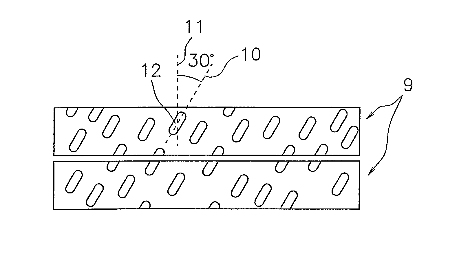
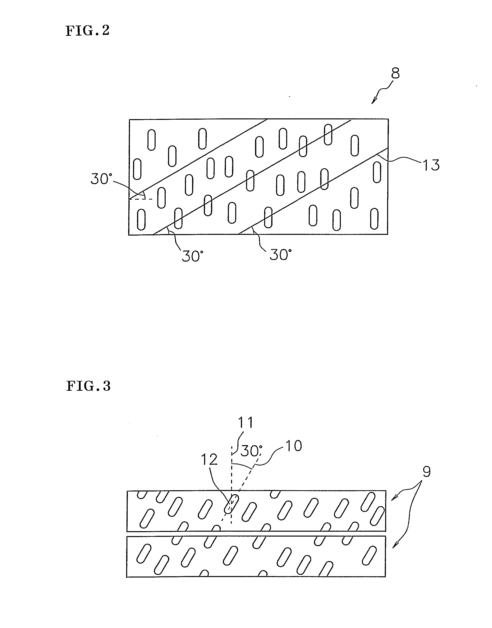
[0054]In the casting step, about 50 volume % of a foaming reaction liquid is injected into a mold of which one side or an opposite side is movable, and the upper surface of the mold is then covered with an upper lid to clamp the mold. It is preferable that vent holes for discharging an excessive foaming reaction liquid when the mold is compressed are formed in the upper lid of the mold. Thereafter, while the foaming reaction liquid is heated to be reacted and cured in the curing step, the side of the mold is moved to compress the mold, and the state is held until the composition does not flow. The composition is preferably compressed to 50 to 95% of the original horizontal width, and more preferably 80 to 90%. The composition is preferably compressed so that the excessive foaming reaction liquid is sufficiently discharged from the vent holes. In this case, the long axis of each of the oval cells is roughly perpendicular to the moving direction of the side surface of the mol...

case 2

2) Case 2

[0055]In the casting step, about 50 volume % of a foaming reaction liquid is injected into a mold, and the upper surface of the mold is then covered with an upper lid to clamp the mold. It is preferable that vent holes for discharging the excessive foaming reaction liquid when the mold is compressed are formed in at least one side surface of the mold. Thereafter, while the foaming reaction liquid is heated to be reacted and cured in the curing step, the upper lid and / or lower surface of the mold is moved to compress the mold, and the state is held until the composition does not flow. The composition is preferably compressed to 50 to 98% of the original height, and more preferably 85 to 95%. The composition is preferably compressed so that the excessive foaming reaction liquid is sufficiently discharged from the vent holes. In this case, the long axis of each of the oval cells is roughly perpendicular to the moving direction of the upper lid or lower surface of the mold.

case 3

3) Case 3

[0056]In the casting step, a foaming reaction liquid is injected in an amount capable of forming a space into a mold, and the upper surface of the mold is then covered with an upper lid to clamp the mold. Holes for decompressing the inside of the mold are formed in the upper lid. Thereafter, while the foaming reaction liquid is heated to be reacted and cured in the curing step, the inside of the mold is decompressed, and the state is held until the mixed solution does not flow. The composition is preferably compressed to 90 to 30 kPa, and more preferably 90 to 70 kPa. In this case, the long axis of each of the oval cells is roughly parallel to the height direction of the mold.


PUM

PropertyMeasurementUnit
thicknessaaaaaaaaaa
depthaaaaaaaaaa
diameteraaaaaaaaaa

Abstract

An object of the present invention is to provide a polishing pad having high planarization property and capable of making it possible to suppress the occurrence of scratches. A polishing pad of the present invention has a polishing layer having oval cells each with a long axis inclined by 5° to 45° with respect to the direction of the thickness of the polishing layer.

Description

REFERENCE TO RELATED APPLICATIONS[0001]This application is a national stage application under 35 USC 371 of International Application No. PCT / JP2011 / 054859, filed Mar. 3, 2011, which claims the priority of Japanese Patent Application No. 2010-068225, filed Mar. 24, 2010, the entire contents of which are incorporated herein by reference.FIELD OF THE INVENTION[0002]The invention relates to a polishing pad capable of performing planarization materials requiring a high surface planarity such as optical materials including a lens and a reflective mirror, a silicon wafer, a glass substrate or an aluminum substrate for a hard disk and a product of general metal polishing with stability and a high polishing efficiency. A polishing pad of the invention is preferably employed, especially, in a planarization step of a silicon wafer or a device on which an oxide layer or a metal layer has been formed prior to further stacking an oxide layer or a metal layer thereon.BACKGROUND OF THE INVENTION[0...

Claims


Application Information

Patent Timeline
Patent Type & Authority Patents(United States)
IPC IPC(8): B24D11/00B24B37/24H01L21/304
CPCB24B37/24B24B37/26H01L21/304
Inventor KAZUNO, ATSUSHI
Owner ROHM & HAAS ELECTRONICS MATERIALS CMP HLDG INC
Why Eureka
Try Eureka