Transformable cable reels and related assemblies and methods
a technology of transformers and reels, applied in the field of transformers, can solve the problems of inconvenient storage of inability to store excess fiber optic cables, etc., and achieve the effects of convenient storage and neat storage of excess cables, less volume, and convenient storage and reus
- Summary
- Abstract
- Description
- Claims
- Application Information
AI Technical Summary
Benefits of technology
Problems solved by technology
Method used
Image

Examples
Embodiment Construction
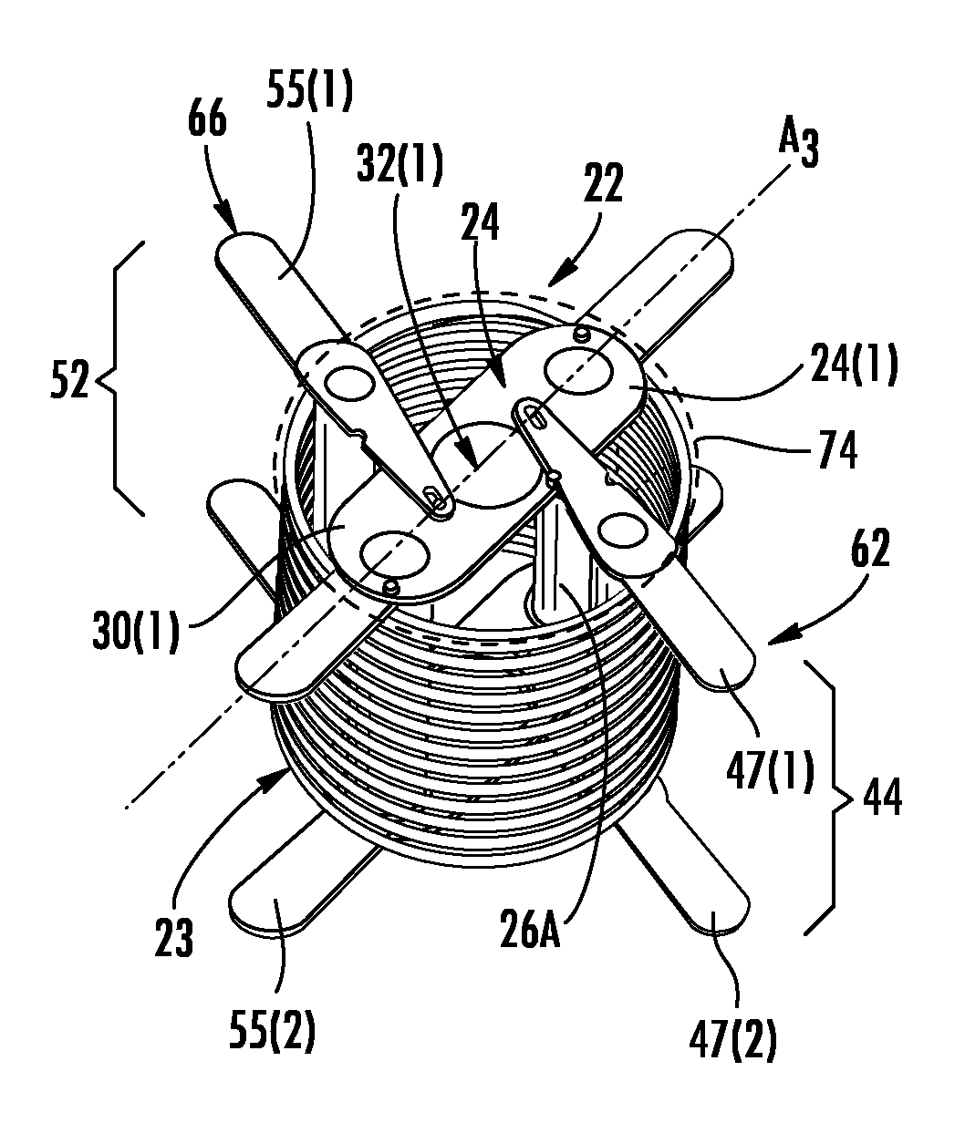
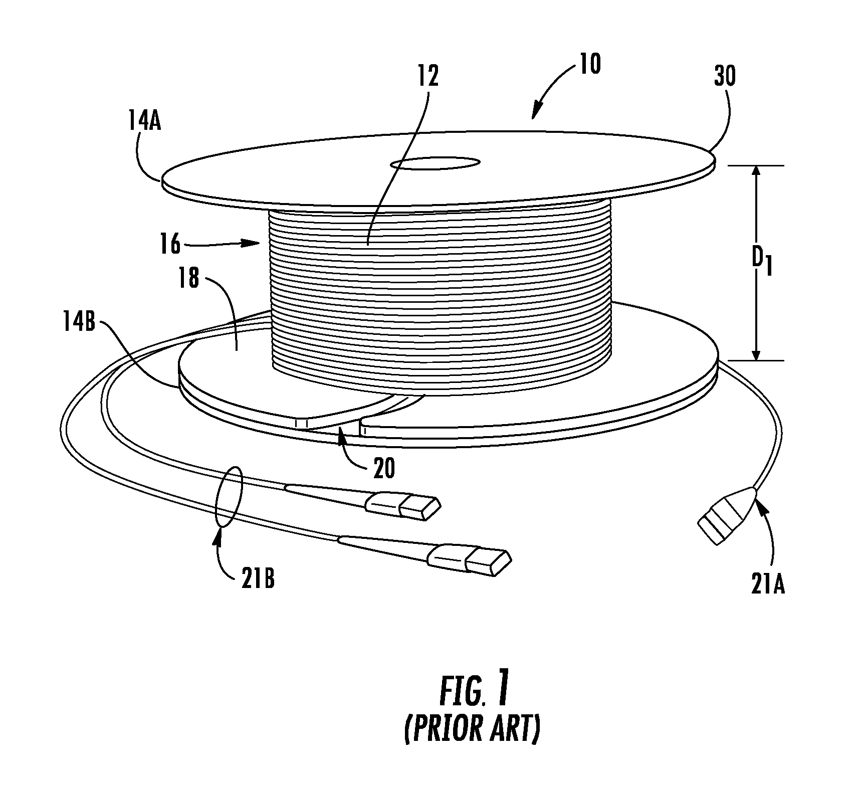
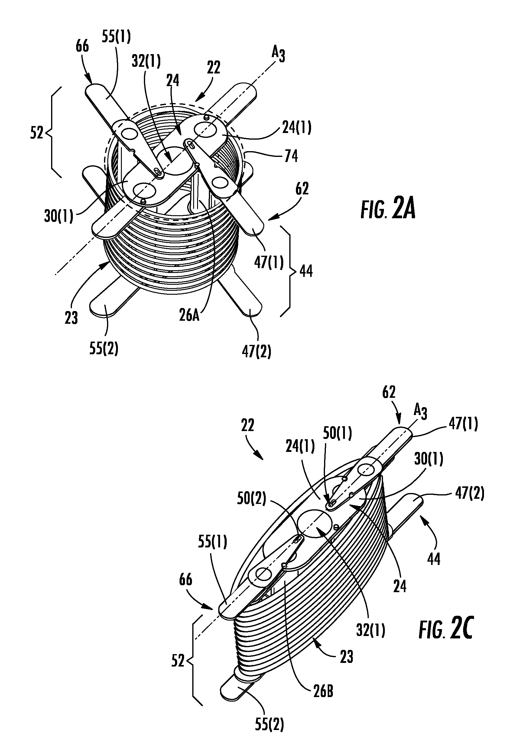
[0009]Embodiments disclosed in the detailed description include transformable cable reels, related assemblies and methods. The transformable cable reels may be employed for fiber optic cable or other types of cable, as non-limiting examples. The transformable cable reels disclosed herein may be provided or disposed in a first reel configuration for spooling on cable to the transformable cable reel and to pay out the spooled cable from the transformable cable reel, such as during cable installations. Cable may be spooled onto the transformable cable reel employing the assistance of external spooling devices and winding fixtures, if desired. Cable spooled on the transformable cable reel may then be payed out from the transformable cable reel. The transformable cable reel may also be configured in a second reel configuration that may be utilized to efficiently and neatly store any excess cable after payout of cable. As one non-limiting example, the volume of the cable reel may be less ...
PUM
 Abstract
Description
Claims
Application Information
 - R&D
- Intellectual Property
- Life Sciences
- Materials
- Tech Scout
- Unparalleled Data Quality
- Higher Quality Content
- 60% Fewer Hallucinations
Browse by: Latest US Patents, China's latest patents, Technical Efficacy Thesaurus, Application Domain, Technology Topic, Popular Technical Reports.
© 2025 PatSnap. All rights reserved.Legal|Privacy policy|Modern Slavery Act Transparency Statement|Sitemap|About US| Contact US: help@patsnap.com