
Wireless communication device

a communication device and wireless technology, applied in the direction of simultaneous aerial operations, electrical equipment, antennas, etc., can solve the problems of inability to support the band better, and the physical characteristics of the antenna, so as to achieve the effect of improving the gain of the antenna elemen

Active Publication Date: 2016-04-05
ACER INC
View PDF8 Cites 0 Cited by
  • Summary
  • Abstract
  • Description
  • Claims
  • Application Information

AI Technical Summary

Benefits of technology

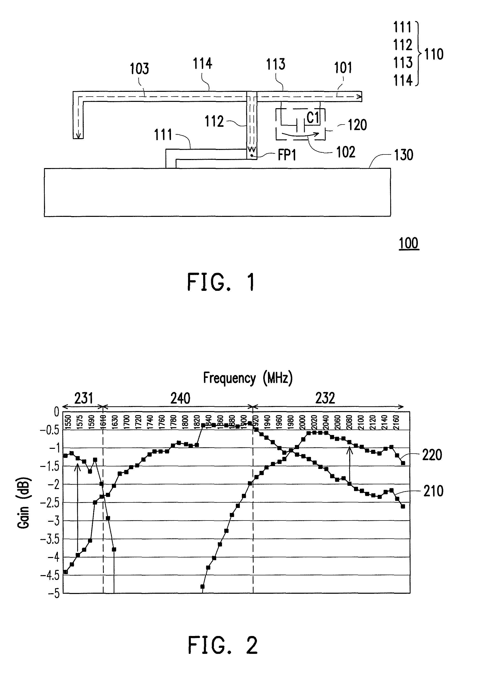
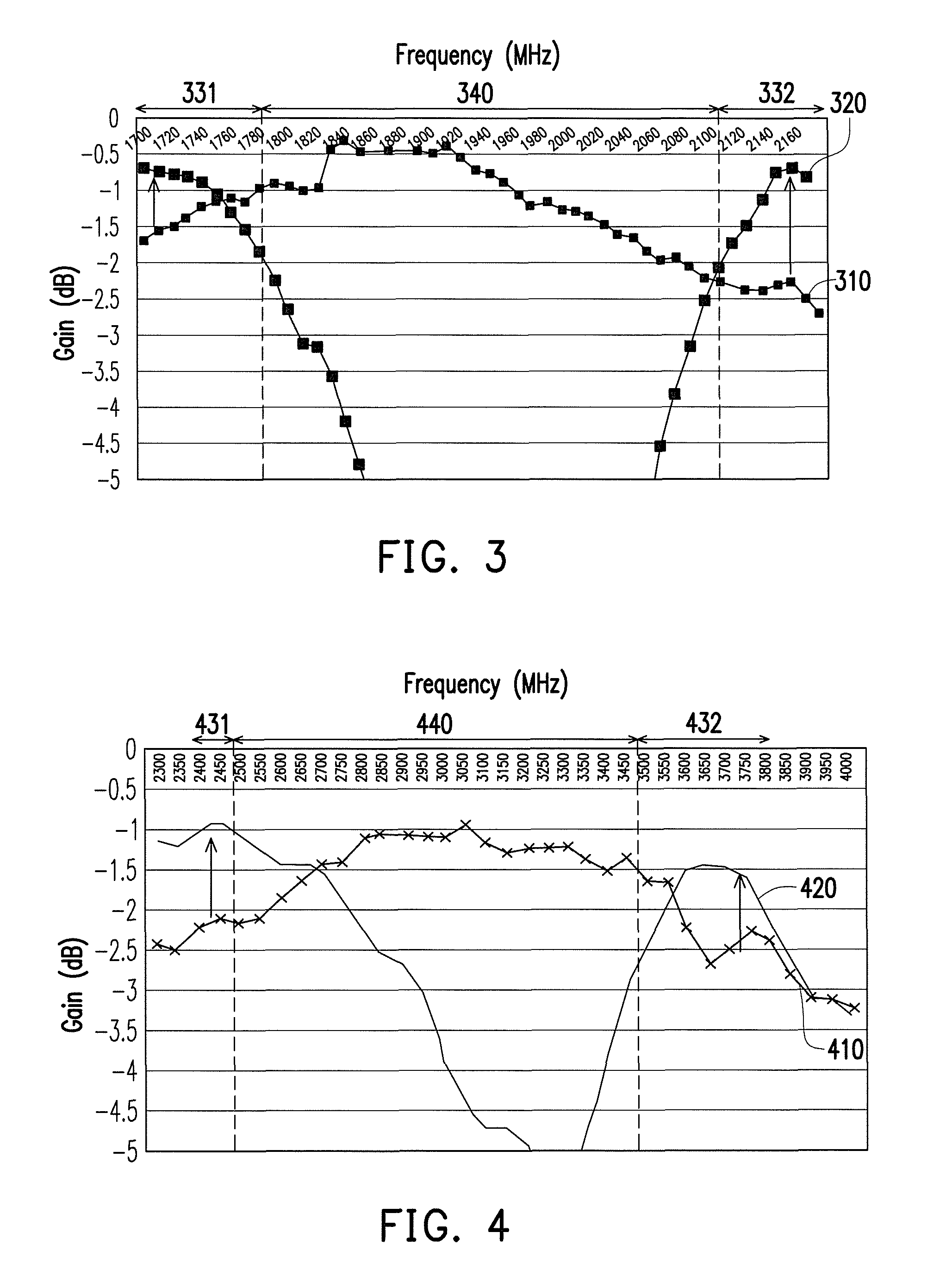
[0009]According to the above descriptions, the antenna element of the invention has a resonant path, and the current path provided by the resonant divider is connected in parallel with a part of the resonant path. Therefore, the operation frequency of the antenna element can cover the first band and the second band without covering the interval band between the first band and the second band. In this way, the energy of the antenna element can be focused on the first band and the second band to satisfy an application demand of the wireless communication device.

Problems solved by technology

However, conventional techniques are generally limited by physical characteristics of the antenna, so that an operable frequency range of the antenna element is designed to be from 1565 MHz to 2170 MHz, directly.
Therefore, the antenna element cannot have a better gain on the bands required to be supported, such that performance of the wireless communication device is influenced in an actual application.

Method used


Image

  • Wireless communication device
  • Wireless communication device
  • Wireless communication device

Examples


Embodiment Construction

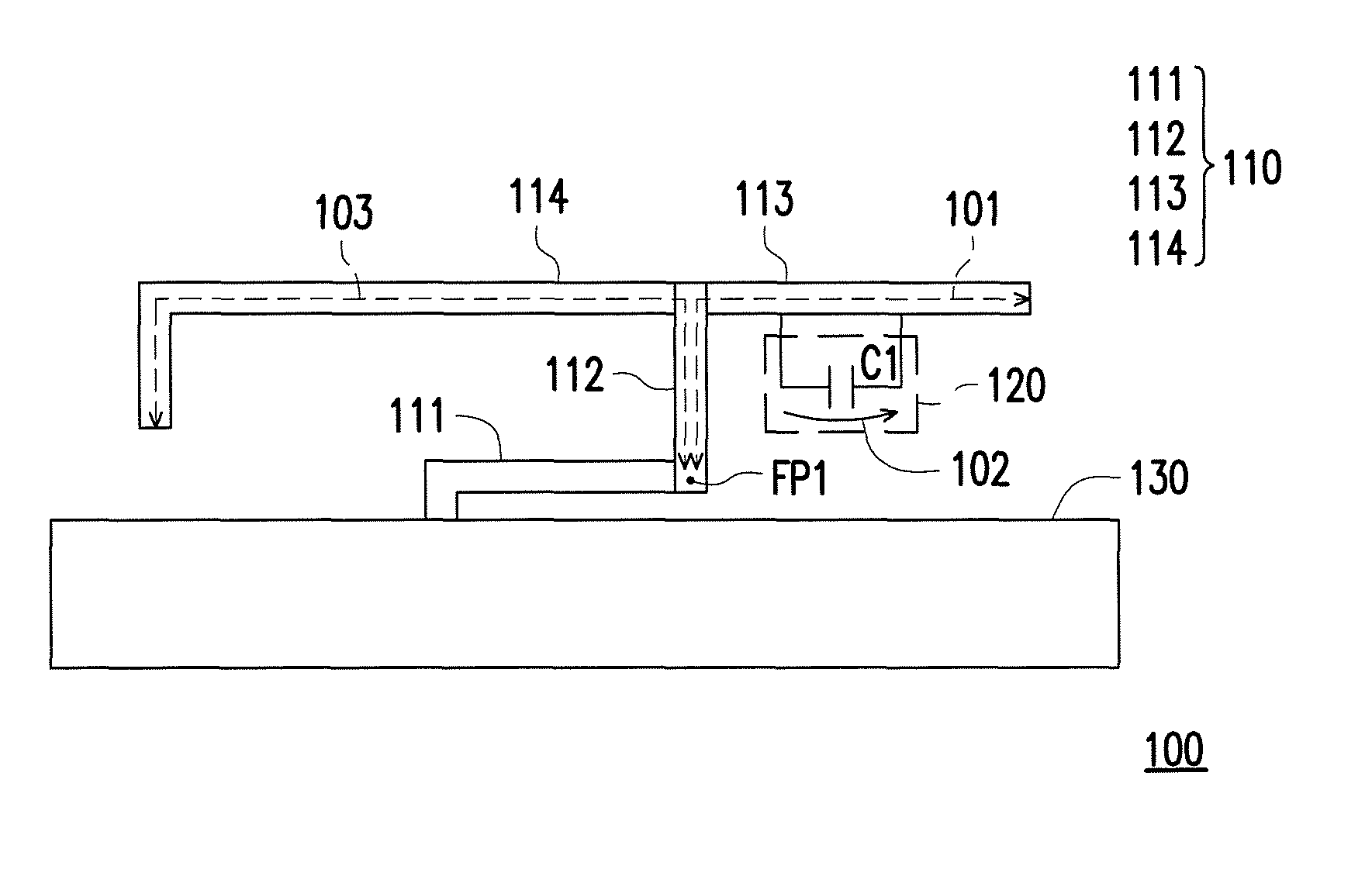
[0016]FIG. 1 is a schematic diagram of a wireless communication device according to an embodiment of the invention. As shown in FIG. 1, the wireless communication device 100 includes an antenna element 110 and a resonant divider 120. The antenna element 110 is, for example, a planar inverted-F antenna (PIFA), and the antenna element 110 includes a ground portion 111, a connection portion 112, a first extending portion 113 and a second extending portion 114.

[0017]In detail, a first terminal of the ground portion 111 is electrically connected to a ground plane 130. A first terminal of the connection portion 112 has a feed point FP1, and the first terminal of the connection portion 112 is electrically connected to a second terminal of the ground portion 111. A first terminal of the first extending portion 113 is electrically connected to a second terminal of the connection portion 112, and a second terminal of the first extending portion 113 is an open terminal. A first terminal of the...


PUM


Abstract

A wireless communication device including an antenna element and a resonant divider is provided. The antenna element has a resonant path so that an operation frequency of the antenna element covers a first band and a second band. The resonant divider is electrically connected to the antenna element and provides a current path connected in parallel with a part of the resonant path. The resonant divider delays a current flowing through the current path so that the antenna element is incapable of covering an interval band between the first band and the second band.

Description

CROSS-REFERENCE TO RELATED APPLICATION[0001]This application claims the priority benefit of Taiwan application serial no. 102149314, filed on Dec. 31, 2013. The entirety of the above-mentioned patent application is hereby incorporated by reference herein and made a part of this specification.BACKGROUND[0002]1. Technical Field[0003]The invention relates to a wireless communication device. Particularly, the invention relates to a wireless communication device having a resonant divider.[0004]2. Related Art[0005]In recent years, wireless communication devices are constantly developed toward a design trend of high performance and multifunction. Therefore, the wireless communication device has to support a plurality of communication protocols, so as to provide diversified services. In order to satisfy various communication protocols, an antenna element in the wireless communication device has to be able to operate in multiple bands. For example, in 3rd generation (3G) mobile communication...

Claims


Application Information

Patent Timeline
Patent Type & Authority Patents(United States)
IPC IPC(8): H01Q5/314H01Q5/00
CPCH01Q5/314H01Q5/321H01Q5/371
Inventor CHANG, KUN-SHENGCHOU, MING-YULIN, CHING-CHI
Owner ACER INC
Learn More