Fitting for a vehicle seat and vehicle seat
a vehicle seat and seat technology, applied in the direction of bearings, shafts and bearings, bearings, etc., can solve the problems of loss of coverage, loss of carrying action in the tooth arrangement, and the insufficient assurance of radial pretensioning required for the prevention of axial drifting
Active Publication Date: 2016-04-05
KEIPER SEATING MECHANISMS CO LTD
View PDF19 Cites 2 Cited by
- Summary
- Abstract
- Description
- Claims
- Application Information
AI Technical Summary
Benefits of technology
This solution enables the use of thin-walled plastics-coated plain bearings with reduced thermal distortion and lower actuation torque, enhancing the fitting's strength and operational efficiency while eliminating the need for costly clinching or laser welding of bush ends, thus improving assembly and operational strength.
Problems solved by technology
A resulting deformation of the plain bearing bush in the event of a crash leads to a loss of coverage and consequently to a loss of carrying action in the tooth arrangement in the region of the tooth engagement between the fitting members.
However, a thin wall thickness, in particular of less than 1 mm, leads to the occurrences of radial pretensioning required for the prevention of axial drifting no longer being adequately ensured.
The formation of the securing region is limited by the ability of the plain bearing bush material to become shaped.
High tolerance requirements on the bearing location require a comparatively complex shaping process.
The use of plain bearing bushes which comprise a material which is rolled through 360° with unconnected opposing ends, is therefore not possible, or possible only to a very limited extent.
This materially integral connection is necessary since, with a plain bearing ring which is arranged at the outer side of an extruded collar, the problem arises that in particular no slotted rings can be calibrated since sufficient tensions cannot be built up for engaging securing with frictional force between the plain bearing ring and the extruded collar.
Method used
View moreImage
Smart ImageViewing Examples
Examples
first embodiment
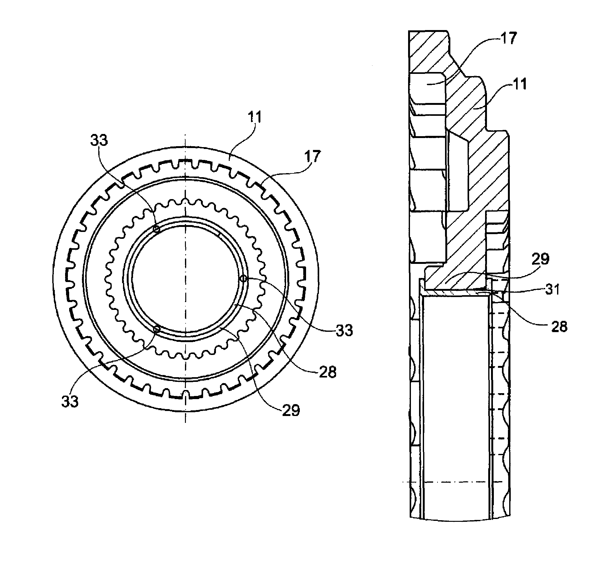
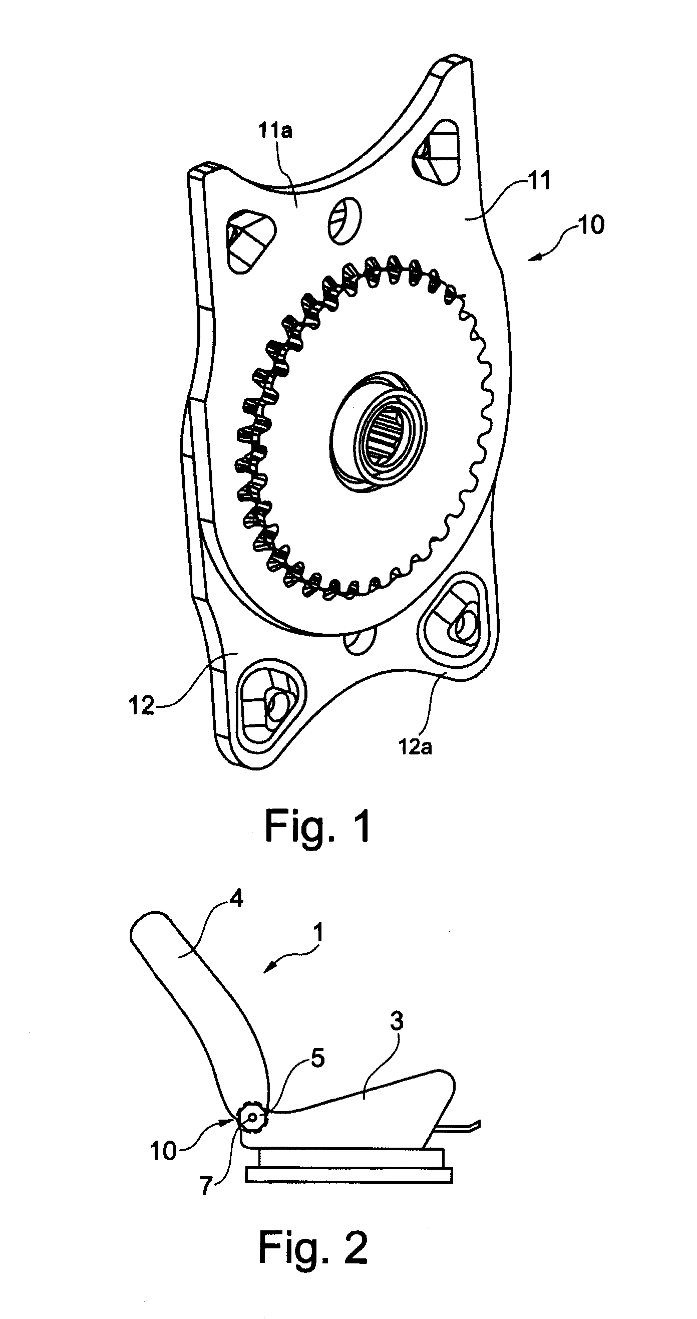
[0025]FIG. 1 is a perspective view of the first embodiment,
[0026]FIG. 2 is a schematic illustration of a vehicle seat having a fitting,
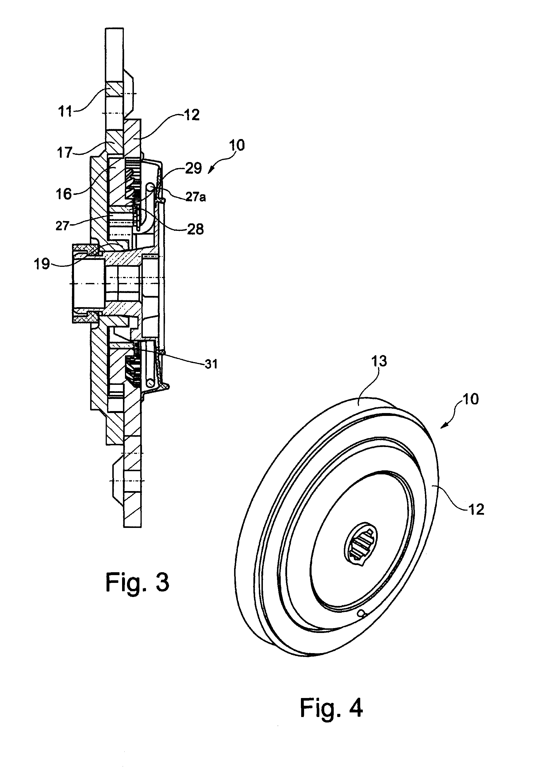
[0027]FIG. 3 is an axial section through the first embodiment,
second embodiment
[0028]FIG. 4 is a perspective view of the second embodiment,
[0029]FIG. 5 is an axial section through the second embodiment,
third embodiment
[0030]FIG. 6 is an axial section through the third embodiment,
Login to View More PUM
 Abstract
A fitting for a vehicle seat, such as a motor vehicle seat, includes a first fitting part, on which a ring gear is formed, and a second fitting part, on which a spur gear is formed, which meshes with the ring gear. The two fitting parts are in transmission connection with each other. A rotatably supported eccentric rotates in the circumferential direction for driving a relative rolling motion of the spur gear and the ring gear. The outside of the eccentric is arranged in a plain bearing bushing in the radial direction. The plain bearing bushing is arranged in a bearing seat, such as a collar of the first or second fitting part. The plain bearing bushing has a wall thickness of less than 1 mm and is connected to the bearing seat in a bonded manner by laser welding. A running side of the plain bearing bushing is plastic-coated.
Description
CROSS REFERENCE TO RELATED APPLICATIONS[0001]The present application is a National Stage of International Application No. PCT / EP2012 / 004425 filed on Oct. 23, 2012, which claims the benefit of German Patent Application Nos. 10 2011 117 392.0 filed on Oct. 25, 2011, and 10 2012 000 296.3 filed Jan. 6, 2012, the entire disclosures of which are incorporated herein by reference.[0002]The invention relates to a fitting for a vehicle seat having a first fitting member on which a toothed ring is formed and a second fitting member on which a toothed wheel is formed and engages with the toothed ring, whereby the two fitting members are connected to each other in gearing terms, and having a rotatably supported eccentric which extends in a peripheral direction for driving a relative rolling movement of the toothed wheel and toothed ring, the eccentric being arranged in a radial direction with the outer side thereof in a plain bearing bush which is arranged in a bearing seat, in particular in an...
Claims
Login to View More Application Information
Patent Timeline
 Patent Type & Authority Patents(United States)
IPC IPC(8): F16C17/12B60N2/225F16C17/06
CPCF16C17/12B60N2/225B60N2/2252F16C17/065
Inventor SCHOLZ, GRIT
Owner KEIPER SEATING MECHANISMS CO LTD
Features
- R&D
- Intellectual Property
- Life Sciences
- Materials
- Tech Scout
- Unparalleled Data Quality
- Higher Quality Content
- 60% Fewer Hallucinations
Learn More Browse by: Latest US Patents, China's latest patents, Technical Efficacy Thesaurus, Application Domain, Technology Topic, Popular Technical Reports.
© 2025 PatSnap. All rights reserved.Legal|Privacy policy|Modern Slavery Act Transparency Statement|Sitemap|About US| Contact US: help@patsnap.com


