Osteosynthesis pin

a technology of osteosynthesis and osteosynthesis nail, which is applied in the field of osteosynthesis nail and osteosynthesis pin, can solve the problems of increasing cutaneous complications, or even necroses, and using simple fractures, so as to reduce the risk of infection for patients, improve bone consolidation, and reduce the effect of patient convalescen

Active Publication Date: 2016-04-05
FOURNITURES HOSPITALERES IND
View PDF7 Cites 0 Cited by
  • Summary
  • Abstract
  • Description
  • Claims
  • Application Information

AI Technical Summary

Benefits of technology

[0008]The technical problem at the base of the invention therefore comprises providing an osteosynthesis pin or osteosynthesis nail that has a simple and cost-effective structure, while limiting the risks of infection for the patient and favoring bone consolidation.
[0010]The structure of the pin according to the invention makes it possible to insert the latter into the patient's bone by making a small cutaneous incision, and thereby limits the risks of infection for the patient.
[0011]Furthermore, the presence of the through-holes formed in the body of the pin makes it possible to assemble, stably using osteosynthesis screws, the fractured bone fragments to the main part of the bone in which the pin is implanted.
[0012]The presence of the axial bore and the at least one oblong opening formed in the body in particular allow the insertion of a curved ancillary instrument, such as a graft remover, or a curved pin inside the body from the outside of the foot and the passage of the free end thereof through the opening so as to cooperate with the fractured fragments to put them back into place. The presence of the axial bore and the at least one oblong opening also allows the passage of an arthroscopic camera so as to verify that replacement of the fractured fragments.
[0013]Further, the fact that the body includes an axial bore extending over the entire length thereof makes it possible to reposition the bone cylinder obtained during the preparation of the bone designed to receive the pin, i.e., during the performance of bone drilling designed to receive the pin, inside the body, which then acts as an arthrodesis cage. These arrangements make it possible to further improve the bone consolidation, and also to decrease the convalescence of the patient.

Problems solved by technology

Such a technique avoids any risk of infection for the patient, but can only be used for simple fractures, i.e., without moving fractured bone fragments.
The implantation of such an osteosynthesis plate makes it possible to ensure satisfactory stabilization of the fractured bone fragments, but often leads to cutaneous complications, or even necroses.
Furthermore, the implantation of such an osteosynthesis plate requires a large cutaneous incision, which increases the risks of infection for the patient.

Method used


Image

  • Osteosynthesis pin
  • Osteosynthesis pin
  • Osteosynthesis pin

Examples


Embodiment Construction

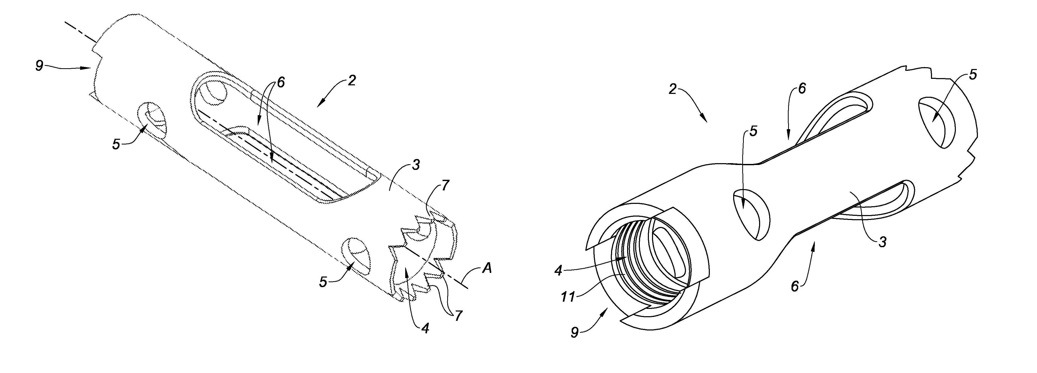
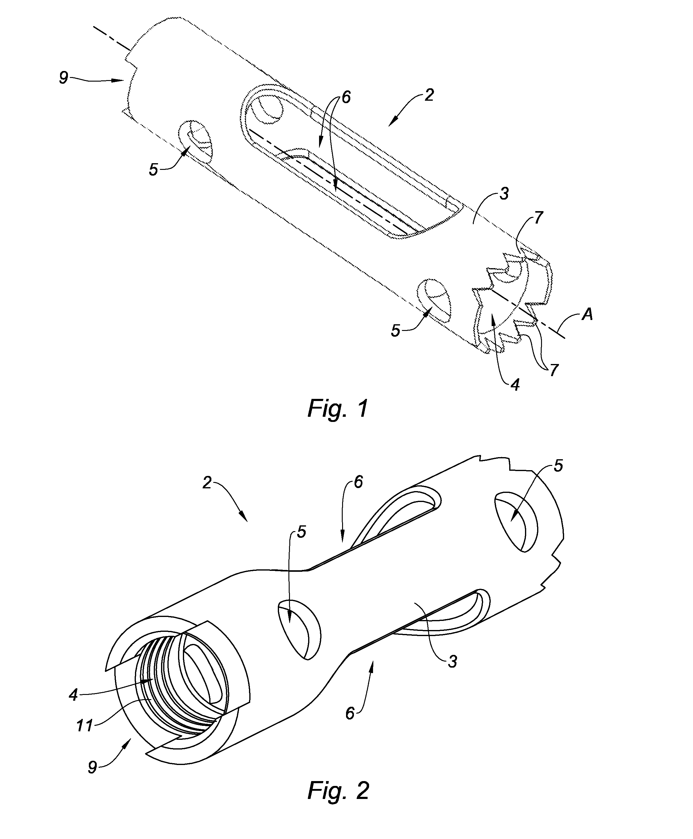
[0029]FIGS. 1 and 2 show an osteosynthesis pin 2 or osteosynthesis nail 2 for a fracture of a calcaneum.

[0030]The osteosynthesis pin 2 comprises a generally cylindrical hollow body 3. The body 3 has a length for example comprised between 30 and 70 mm, and is made from a biocompatible material, such as stainless steel or titanium alloy. The body advantageously has an outer diameter comprised between 8 and 15 mm.

[0031]The hollow body 3 includes an axial bore 4 extending over the entire length thereof, with a substantially circular cross-section.

[0032]The hollow body 3 includes an axial bore 4 extending over the entire length thereof, and with a substantially circular cross-section.

[0033]The hollow body 3 also includes a plurality of through-holes 5 longitudinally staggered relative to one another and designed for the passage of fastening screws. The axes of the through-holes 5 are substantially parallel to each other and extend substantially perpendicular to the axis A of the pin.

[003...


PUM


Abstract

The invention relates to an osteosynthesis pin, in particular for a fracture of a calcaneum, made up of a generally cylindrical hollow body comprising an axial bore extending over the entire length thereof, a plurality of through-holes staggered longitudinally relative to one another and intended for attachment screws to pass therethrough, and at least one oblong opening suitable for an ancillary instrument to pass therethrough for repositioning fractured bone fragments.

Description

TECHNICAL FIELD[0001]The present invention relates to an osteosynthesis pin or osteosynthesis nail, and more particularly an osteosynthesis pin for a fracture of a calcaneum.BACKGROUND[0002]Different operating techniques exist to consolidate a bone fracture, and more particularly a fracture of a calcaneum.[0003]A first known technique consists of immobilizing the patient's foot in a cast. Such a technique avoids any risk of infection for the patient, but can only be used for simple fractures, i.e., without moving fractured bone fragments.[0004]Complex fractures, i.e., that require moving fractured bone fragments, must be treated surgically using various osteosynthesis means.[0005]A first surgical technique consists of inserting traditional osteosynthesis screws or so-called “compression” osteosynthesis screws into the fractured bone fragments so as to secure the latter to the main part of the bone in order to allow natural bone consolidation of the fracture site. Such screws may be ...

Claims


Application Information

Patent Timeline
Patent Type & Authority Patents(United States)
IPC IPC(8): A61B17/04A61B17/84A61B17/86A61F2/08A61B17/72
CPCA61B17/864A61B17/7258A61B17/7291A61B17/7233
Inventor GOLDZAK, MARIOSIMON, PATRICKMITTLMEIER, THOMASHUNT, FRANCK
Owner FOURNITURES HOSPITALERES IND
Why Eureka
Try Eureka