
Nose cone for dust control

a technology of nose cone and dust control, which is applied in the direction of conveyors, loading/unloading, transportation and packaging, etc., can solve the problems of silicosis, bronchitis or cancer, silicosis, or cancer, and the risk of occupational diseases

Inactive Publication Date: 2016-03-29
ASSOC RES - EDC
View PDF17 Cites 48 Cited by
  • Summary
  • Abstract
  • Description
  • Claims
  • Application Information

AI Technical Summary

Benefits of technology

The patent describes a nose cone that can be used to contain respirable and inhalable particles created in an industrial process. The nose cone is made of a material sheet that has an upper edge, a lower edge, a first side edge, and a second side edge. The material sheet is wrapped to form an overlap between the first and second side edges. The open upper end of the nose cone has an upper diameter and the open lower end has a lower diameter, with the upper diameter being smaller than the lower diameter. The material sheet is secured at the overlap using at least one attachment mechanism, such as cable ties, fasteners, adjustable connectors, or adhesives. The open upper end of the nose cone is sealable with the tail spout and the vacuum hose. The technical effect of this invention is to provide a simple and effective way to contain respirable and inhalable particles created in an industrial process.

Problems solved by technology

Inhalable and / or respirable silica dioxide (SiO2) is a major problem facing the oil and gas (O&G) industry.
Silica dioxide is particularly hazardous when it is broken down, creating inhalable or respirable silica dust (very small crystalline particles and / or amorphous particles).
The Center for Construction Research and Training has stated that “inhaling crystalline silica dust can lead to silicosis, bronchitis, or cancer as the dust becomes lodged in the lungs and continuously irritates them.” According to the World Health Organization (WHO), whenever people inhale airborne dust at work, they are at risk of occupational disease.
Year after year, both in developed and in developing countries, overexposure to dusts causes disease, temporary and permanent disabilities and deaths.
Dusts in the workplace may also contaminate or reduce the quality of products, be the cause of fire and explosion, and damage the environment.
Further, the proppants tend to breakdown during handling (loading, transportation, and unloading).
The breakdown of the proppants results in respirable silica.
Respirable silica has recently been recognized as a hazard in fracking operations, which can use between several tons to two million pounds of frac sand per well site.
The vacuum hose has to be laid correctly or problems may ensue.
If the vacuum hose is placed too close to the frac sand, the hose can end up sucking up sand.
If the vacuum hose is placed too far away from the frac sand, the hose does not effectively remove the silica dust.
Another problem is that the tent structure can block the operator's sightlines.
Even if an opening is made in the tent structure so that the operator can see what is going on inside the tent structure, the interior of the tent structure can be dark making it difficult to see.
If the tent structure is preventing the operators from seeing what they're doing, it is difficult for the operators to make adjustments to the rate of sand transfer which is critical to the fracturing process.
Adding a window to the tent structure to regain sightlines is impractical for a number of reasons.
An open window will necessarily allow dust to escape because the overall volume of air within the tent is too large for the vacuum hoses to maintain sufficient negative pressure.
Adding a pane of transparent material to the window to contain the dust fails as the window becomes too dirty to see through.
This design often requires that a plurality of vacuum hoses be run along the ground to reach the appropriate spots, which presents a tripping hazard.
Also, if a vacuum hose is not well fixed to its final location, it may shift out of place.
If the tent material is loose, it may be accidentally sucked into the vacuum hose.
Tent structures can be large and cumbersome.
It is not road worthy, and therefore cannot be left on the equipment.
The tent structures are not particularly good at adjusting to changes in the height or position of the tail.
Further, the tent structure may not contain the silica dust at the opening of the tail (e.g. the tail spout), especially when the tail is lifted higher than the top of the tent structure (which occasionally happens).
By creating a large volume space with very high concentrations of silica dust, a health hazard is created if a worker must enter the area to deal with a problem.

Method used


Image

  • Nose cone for dust control
  • Nose cone for dust control
  • Nose cone for dust control

Examples


Embodiment Construction

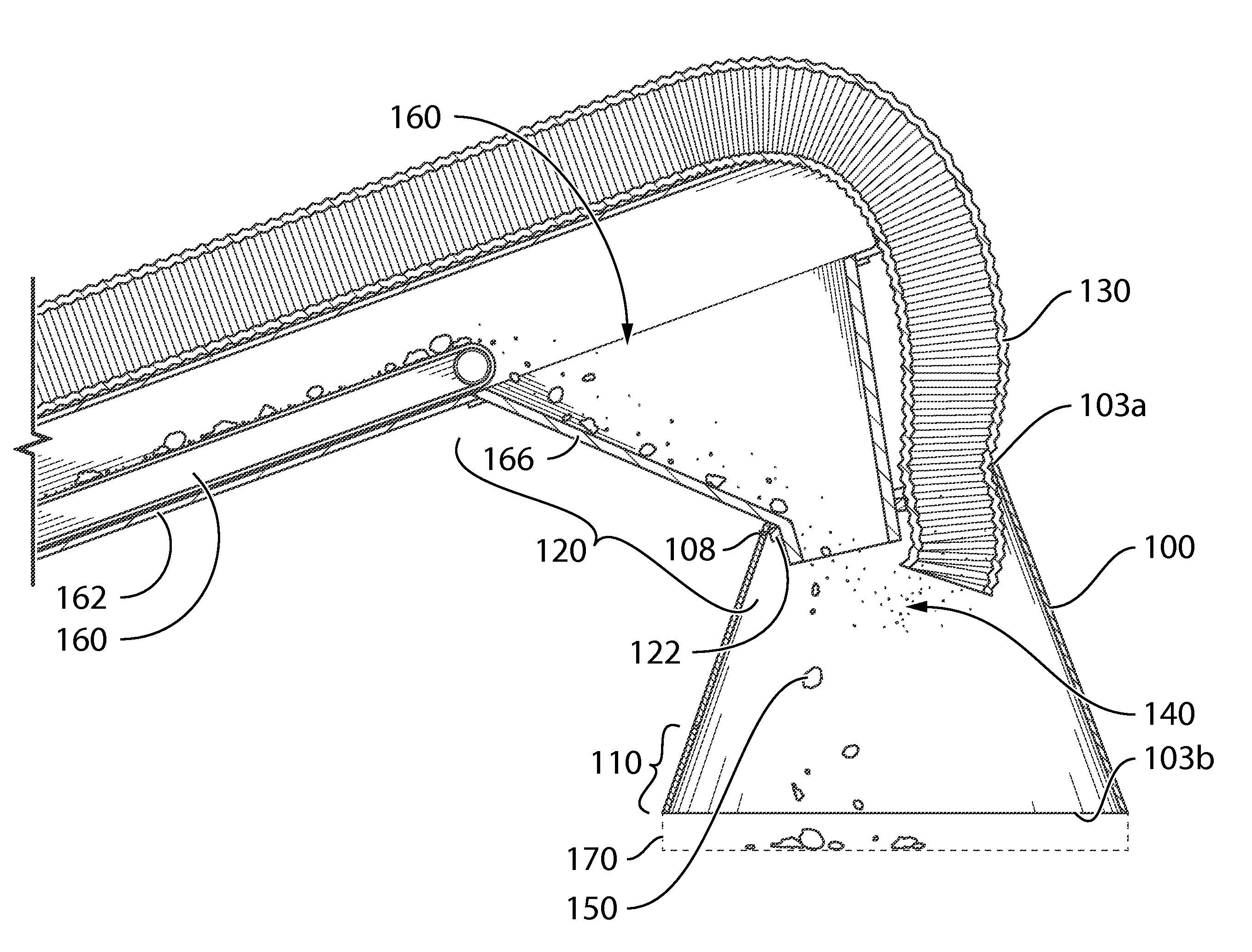
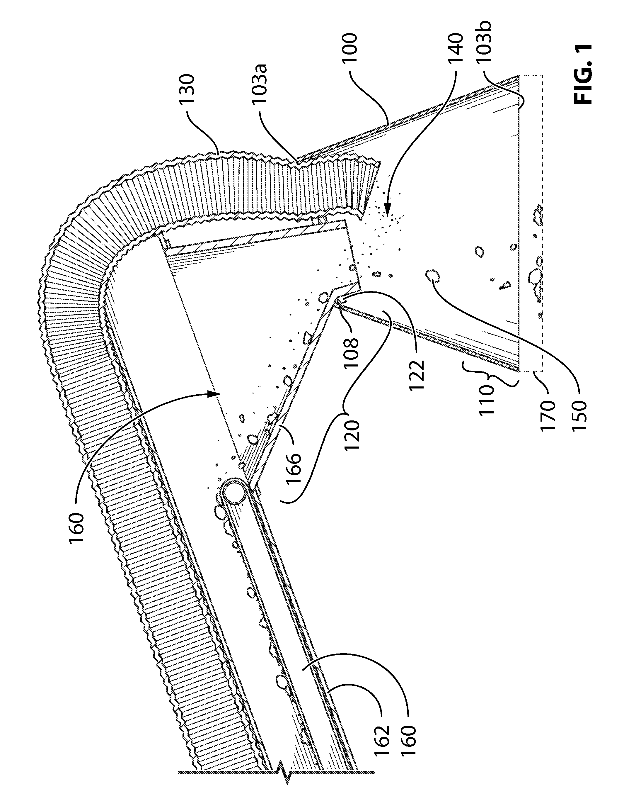
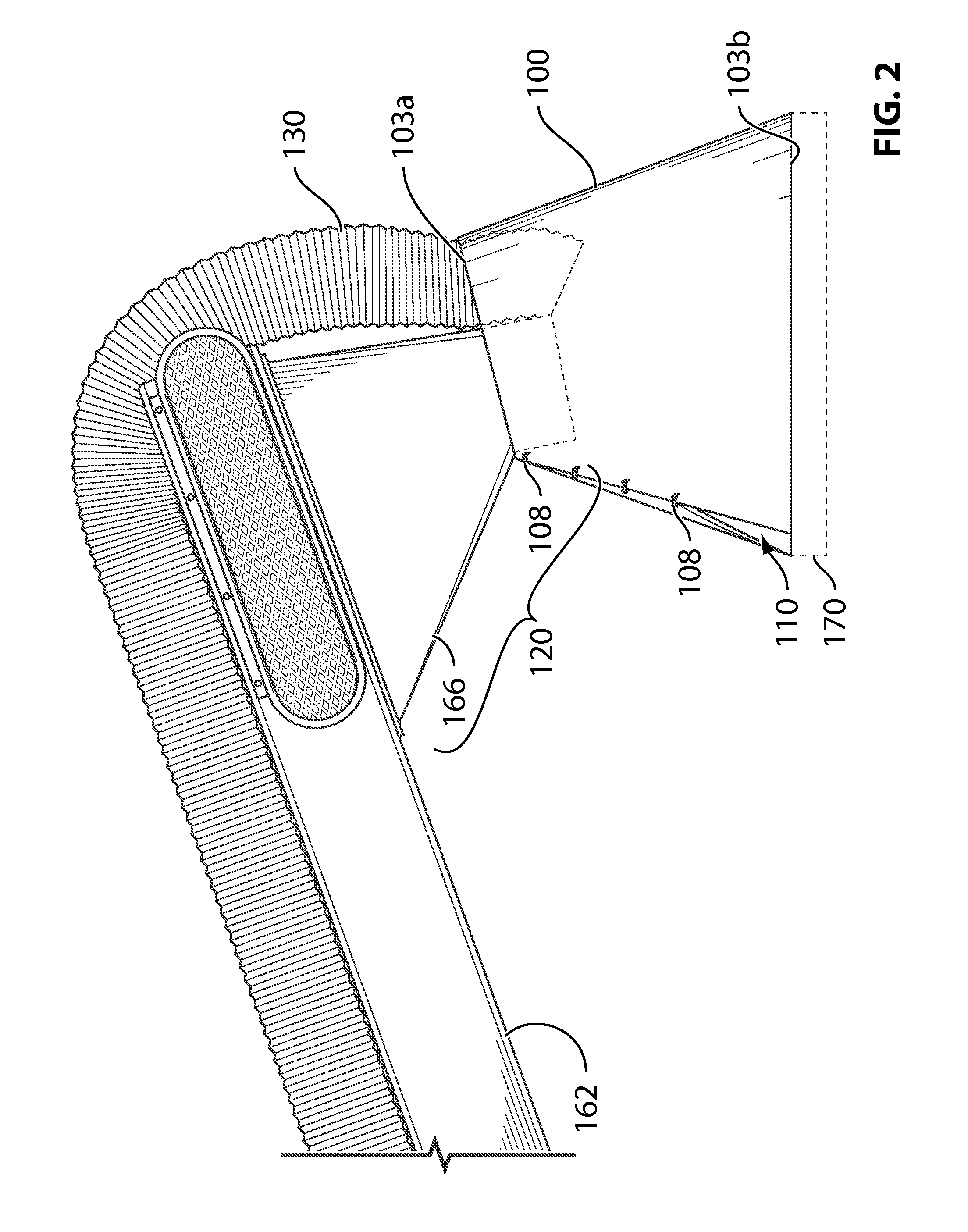
[0030]Described herein is a nose cone 100 with a viewing window 110 and, more specifically, a nose cone 100 with a viewing window 110 being associatable with a tail spout 120 of a sand handler (not shown) and a vacuum hose 130 of a vacuum system (not shown). The nose cone 100 provides an efficient and effective method of containing the dust 140 (e.g. silica dust 140) and / or other dangerous respirable and / or inhalable particles created in industrial processes such as fracking.

[0031]Exemplary nose cones may be better understood with reference to the drawings, but these nose cones are not intended to be of a limiting nature. The same reference numbers will be used throughout the drawings and description in this document to refer to the same or like parts. The shown shapes and relative dimensions are preferred, but are not meant to be limiting unless specifically claimed, in which case they may limit the scope of that particular claim.

DEFINITIONS

[0032]Before describing the nose cones an...


PUM


Abstract

Preferred nose cones 100 associatable with a tail spout 120 of a sand handler and a vacuum hose 130 of a vacuum system are described herein. A method for containing respirable and / or inhalable particles 140 created in an industrial process is also disclosed herein.

Description

[0001]The present application is an application claiming the benefit of U.S. Provisional Patent Application No. 61 / 975,511, filed Apr. 4, 2014. The present application is based on and claims priority from this application, the disclosure of which is hereby expressly incorporated herein by reference in its entirety.BACKGROUND OF THE INVENTION[0002]Described herein is a nose cone with a viewing window and, more specifically, a nose cone with a viewing window being associatable with a tail spout of a sand handler and a vacuum hose of a vacuum system.[0003]Inhalable and / or respirable silica dioxide (SiO2) is a major problem facing the oil and gas (O&G) industry. Silica dioxide is a commonly occurring element found in two forms—crystalline and amorphous. Quartz and sand are common examples of crystalline silica. Silica dioxide is particularly hazardous when it is broken down, creating inhalable or respirable silica dust (very small crystalline particles and / or amorphous particles). The C...

Claims


Application Information

Patent Timeline
Patent Type & Authority Patents(United States)
IPC IPC(8): B65G19/28B65G69/18
CPCB65G69/186
Inventor HOUGHTON, GORDON, GERALDTEMPLETON, MATTHEW, CHARLES
Owner ASSOC RES - EDC
Learn More