Ranging apparatus, imaging apparatus, and ranging method

a technology of ranging apparatus and ranging method, which is applied in the field of ranging apparatus and imaging apparatus, can solve the problems of increasing production cost, reducing calculation accuracy of image shift amount, and ineffective correction of light quantity balance between a-image and b-image, so as to reduce the calculation error of image shift amount

Active Publication Date: 2016-03-22
CANON KK
View PDF21 Cites 6 Cited by
  • Summary
  • Abstract
  • Description
  • Claims
  • Application Information

AI Technical Summary

Benefits of technology

[0011]With the focus detection method disclosed in Japanese Patent Application Publication No. H2-181108, the correction coefficient is measured after assembling the imaging optical system and the imaging sensor. As a result, the correction of the light quantity ratio of the A-image and B-image is not affected by a production error, and the calculation error of the image shift amount can be reduced.
[0012]However, recently developed digital cameras are equipped with an optical image stabilizer function, and the optical axis of a lens at the time the correction coefficient is calculated can differ from that at the time of actual imaging. Thus, when a correction coefficient that has been acquired in advance is used, the collapse of the light quantity balance of the A-image and B-image is not necessarily corrected effectively, and the calculation accuracy of the image shift amount can decrease. Further, calculating the correction coefficient after assembling the lens and the imaging sensor adds an adjustment step, which can increase the production cost.
[0013]With the focus detection method disclosed in Japanese Patent Application Publication No. 2009-258231, the collapse of the light quantity balance is corrected by taking into account the light quantity ratio of the A-image and B-image when calculating the degree of correlation of a picture image in a search region and a picture image in a reference region, and the ranging accuracy is increased by decreasing the calculation error of the image shift amount.
[0015]Accordingly, it is an objective of the present invention to provide a ranging apparatus in which the collapse of the light quantity balance of the A-image and B-image can be corrected and high-accuracy ranging can be performed with a small computational volume.
[0018]In accordance with the present invention, in a ranging apparatus calculating a distance to an object on the basis of an image shift amount, the image shift amount can be calculated with a high accuracy, and highly accurate ranging can be performed with a small computational volume.

Problems solved by technology

Thus, when a correction coefficient that has been acquired in advance is used, the collapse of the light quantity balance of the A-image and B-image is not necessarily corrected effectively, and the calculation accuracy of the image shift amount can decrease.
Further, calculating the correction coefficient after assembling the lens and the imaging sensor adds an adjustment step, which can increase the production cost.
The increase in the computational volume can result in an increased cost due to the extended processing time and the increased scale of computational circuitry.
Further, since the collapse of the light quantity balance is corrected with consideration for only the A-image and B-image included in the criterion region, the light quantity balance cannot be accurately corrected due to the effect of noise, such as light shot noise.

Method used


Image

  • Ranging apparatus, imaging apparatus, and ranging method
  • Ranging apparatus, imaging apparatus, and ranging method
  • Ranging apparatus, imaging apparatus, and ranging method

Examples


first embodiment

[0037]The first embodiment of the present invention will be explained hereinbelow in detail with reference to the drawings.

[0038]

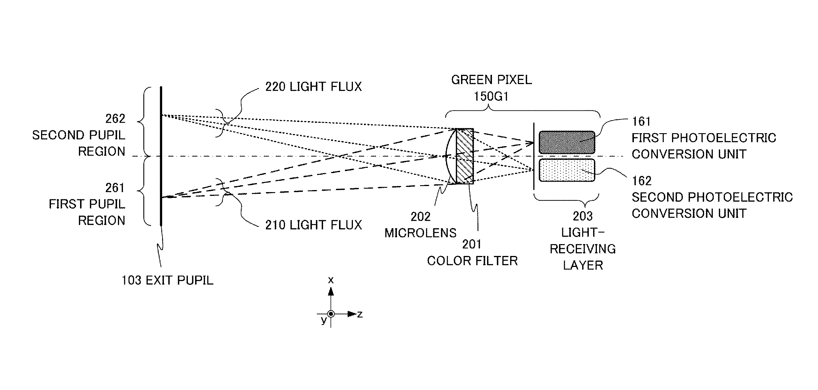
[0039]FIG. 1A shows the configuration of a digital camera 100 of the present embodiment. The digital camera 100 is constituted by disposing an imaging optical system 120, an imaging sensor 101, a ranging unit 102, a picture image generating unit (not shown in the figure), and a lens drive control unit (not shown in the figure) inside a camera housing 130. A ranging apparatus 110 is constituted by the imaging optical system 120, the imaging sensor 101, and the ranging unit 102. The ranging unit 102 can be configured using a logical circuit. The ranging unit 102 may be also configured by a central processing unit (CPU) and a memory storing a computational processing program.

[0040]The imaging optical system 120 is a lens of the digital camera 100 and has a function of forming an image of an object on the imaging sensor 101, which is an imaging surface. The im...

second embodiment

[0117]The second embodiment of the present invention will be described in greater detail with reference to the appended drawings.

[0118]In the explanation below, a digital camera is used as an example of the imaging apparatus provided with the ranging apparatus in accordance with the present invention, but the application of the present invention is not limited thereto. For example, the ranging apparatus in accordance with the present invention can be also used in a digital distance measuring apparatus.

[0119]In the explanation below that refers to the appended drawings, the same segments are assigned with the same reference numerals in different drawings in principle, and the redundant explanation thereof is herein avoided.

[0120]In FIG. 13, the reference numeral 1300 stands for a digital camera equipped with a ranging apparatus 1310 of the present embodiment. The digital camera 1300 is constituted by disposing the imaging optical system 120, the imaging sensor 101, the ranging unit 1...


PUM


Abstract

A ranging apparatus includes: an output ratio data calculation unit for calculating an output ratio data of first and second image data; a correction function calculation unit for calculating a correction function approximating the output ratio data by an N-order function (N being an integer equal to or greater than 1) having a pixel position as a variable; a correction unit for correcting at least one of the first and second image data on the basis of the correction function; and a ranging unit for calculating the defocus amount by using the picture image data corrected by the correction unit.

Description

BACKGROUND OF THE INVENTION[0001]1. Field of the Invention[0002]The present invention relates to a ranging apparatus, an imaging apparatus, and a ranging method.[0003]2. Description of the Related Art[0004]Japanese Patent Application Publication No. 2003-244712 suggests a solid-state imaging sensor for a digital still camera or a digital video camera in which pixels having a ranging function (referred to hereinbelow as “ranging pixels”) are arranged in the entire imaging sensor or part thereof, and the distance to an object is detected by a phase difference method. The ranging pixels are equipped with a plurality of photoelectric conversion units and configured such that light fluxes that have passed through different regions on a lens pupil are guided to different photoelectric conversion units.[0005]Picture image data (a picture image based on an A-image is referred to hereinbelow as “A-picture image”, and a picture image based on a B-image is referred to hereinbelow as “B-picture...

Claims


Application Information

Patent Timeline
Patent Type & Authority Patents(United States)
IPC IPC(8): G03B13/00H04N5/232H04N5/225H04N5/369
CPCH04N5/2254H04N5/3696H04N5/23212H04N23/672H04N25/704H04N25/134H04N23/71H04N23/76
Inventor NOBAYASHI, KAZUYA
Owner CANON KK
Why Eureka
Try Eureka