Method and controller for an electric motor with switch testing

a technology of electric motors and controllers, applied in the direction of motor/generator/converter stoppers, dynamo-electric converter control, instruments, etc., can solve the problems of motors that are difficult to control, controllers, motors damaged,

Active Publication Date: 2016-03-22
DEERE & CO
View PDF10 Cites 9 Cited by
  • Summary
  • Abstract
  • Description
  • Claims
  • Application Information

AI Technical Summary

Benefits of technology

[0003]In accordance with one embodiment, a method and system is presented for testing switches in a controller for an electric motor. For each phase of a controller, a pair of semiconductor switches comprises a high side switch and a low side switch. A direct current voltage bus provides electrical energy to the semiconductor switches at a test voltage level less than a full operational voltage level. A measuring circuit (e.g., voltage sensor) is adapted to measure the direct current bus voltage. A data processor determines that a deficiency (e.g., short circuit or fault) in a tested, related semiconductor switch is present if the measured direct current bus voltage decreases or collapses upon activation of a particular semiconductor switch in the same phase of the controller, or if other sequential test results indicate a deficiency (e.g., an open circuit) in one or more semiconductor switches. If the deficiency in the related semiconductor switch is present, the data processor may prevent the voltage supply from providing the full operational voltage to the direct current data bus to prevent damage to the motor or the controller, for example.

Problems solved by technology

During operation of the motor, if the semiconductor switch fails in either an open state or a closed state, the motor (e.g., motor speed or torque) may be difficult to control, and damage can occur to the controller, the motor, or both.

Method used


Image

  • Method and controller for an electric motor with switch testing
  • Method and controller for an electric motor with switch testing
  • Method and controller for an electric motor with switch testing

Examples


Embodiment Construction

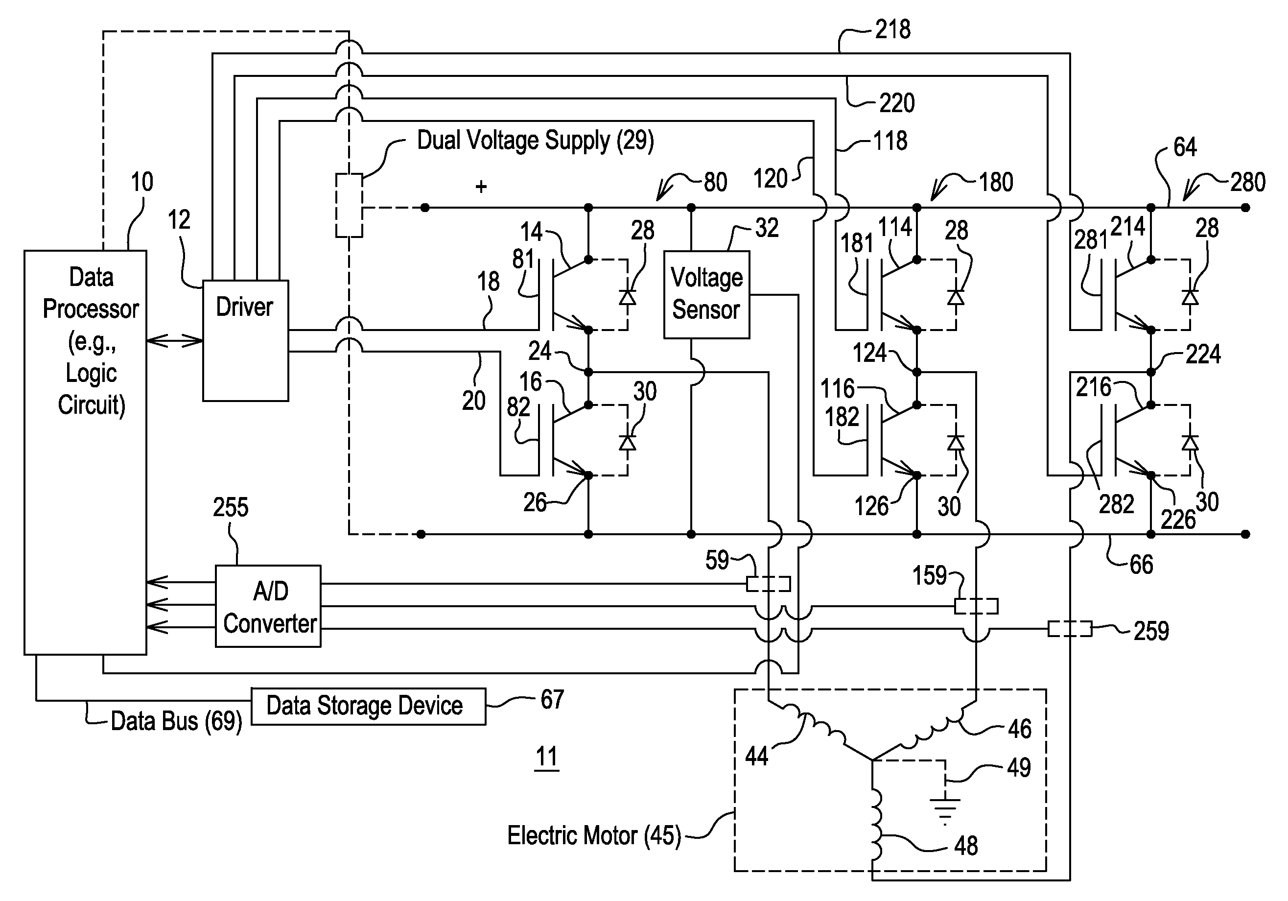
[0014]In accordance with one embodiment, FIG. 1 discloses a system, inverter or controller 11 for controlling an electric motor 45, where the controller 11 is capable of detection of a deficiency in one or more switches of the controller 11 in a test mode at a lower test voltage, prior to operational mode at a higher operational voltage. For example, a deficiency may comprise a short-circuit failure mode or open-circuit failure mode of one or more semiconductor devices in the controller 11. In the test mode, the lower test voltages are less likely to damage the components of the controller 11 or the motor 45 than the higher operational voltage. The electric motor 45 may comprise an interior permanent magnet (IPM) motor 45 of FIG. 1 or another alternating current machine. As illustrated, the system, aside from the motor 45, may be referred to as an inverter or a motor controller 11.

[0015]In FIG. 1, the data processor 10 is coupled to a driver 12 and a dual voltage supply 29. The driv...


PUM


Abstract

For each phase of a controller, a pair of semiconductor switches comprises a high side switch and a low side switch. A direct current voltage bus provides electrical energy to the semiconductor switches at a test voltage level less than a full operational voltage level. A measuring circuit is adapted to measure the direct current bus voltage. A data processor determines that a deficiency in a tested, related semiconductor switch is present if the measured direct current bus voltage decreases or collapses upon activation of a particular semiconductor switch in the same phase of the controller, or if other sequential test results indicate a deficiency. If the deficiency in the related semiconductor switch is present the processor may prevent the voltage supply from providing the full operational voltage to the direct current data bus to prevent damage to the motor or the controller, for example.

Description

FIELD OF THE INVENTION[0001]This invention relates to a method and controller for electric motor with switch testing.BACKGROUND OF THE INVENTION[0002]An electric motor may feature a rotor with permanent magnets and a stator, such as an interior permanent magnet (IPM) motor or an IPM synchronous motor. In accordance with certain prior art, an inverter or motor controller comprises semiconductor switches that support the provision of alternating current outputs for one or more phases of the electric motor. The semiconductor switch may fail in an open state (i.e., discontinuity) or a closed state (i.e., short circuit) with respect to the output terminals of the semiconductor switch. During operation of the motor, if the semiconductor switch fails in either an open state or a closed state, the motor (e.g., motor speed or torque) may be difficult to control, and damage can occur to the controller, the motor, or both. Thus, there is a need for an improved method and controller for an elec...

Claims


Application Information

Patent Timeline
Patent Type & Authority Patents(United States)
IPC IPC(8): G01R31/02G01R31/42H02P29/02G01R31/34G05F3/00H02H7/122H02H7/08G01R31/327H02H7/085
CPCG01R31/42H02H7/0838H02H7/1225G01R31/343G01R31/025G01R31/327H02H7/0852H02P29/0241G01R31/52
Inventor AALUND, WHITNEY M.GILMAN, ALAN K.WU, LONG
Owner DEERE & CO
Why Eureka
Try Eureka