Pneumatic tire
a technology of pneumatic tires and treads, applied in the field of pneumatic tires, can solve the problems of uneven wear, large load high stiffness in the circumferential direction of the tire, and achieve the effect of effective relieved load acting on the tread portion, increased uneven wear resistance of the tire, and reduced friction
- Summary
- Abstract
- Description
- Claims
- Application Information
AI Technical Summary
Benefits of technology
Problems solved by technology
Method used
Image
Examples
modified examples
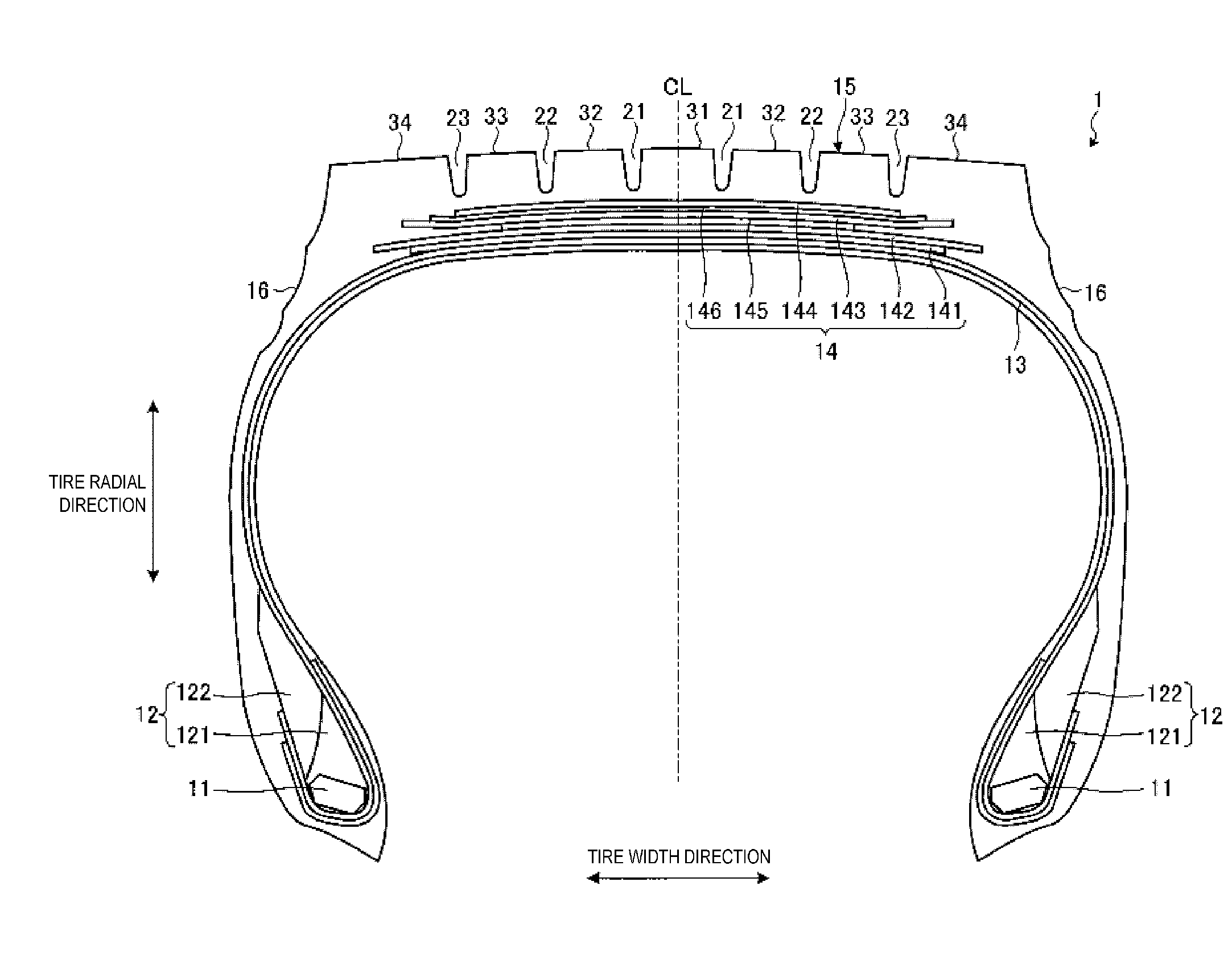
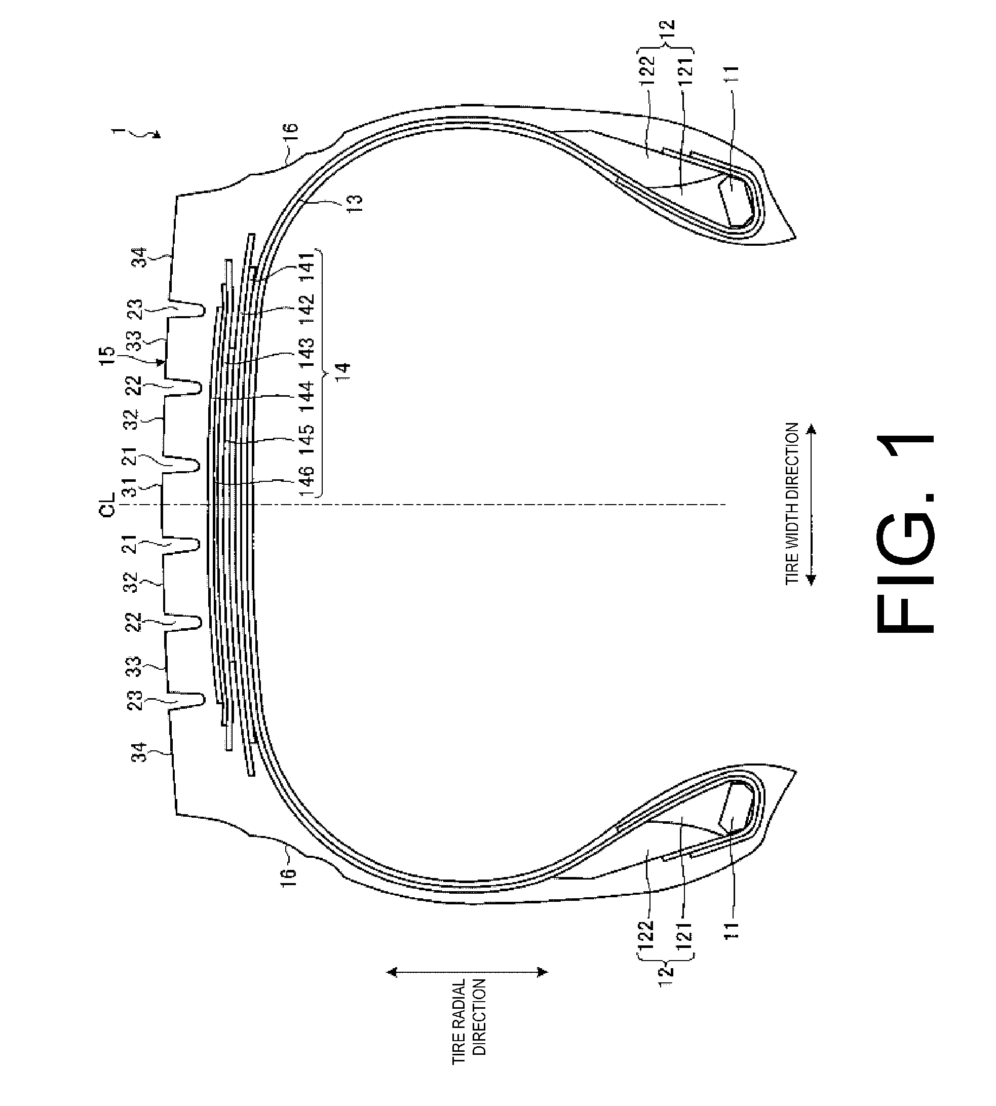
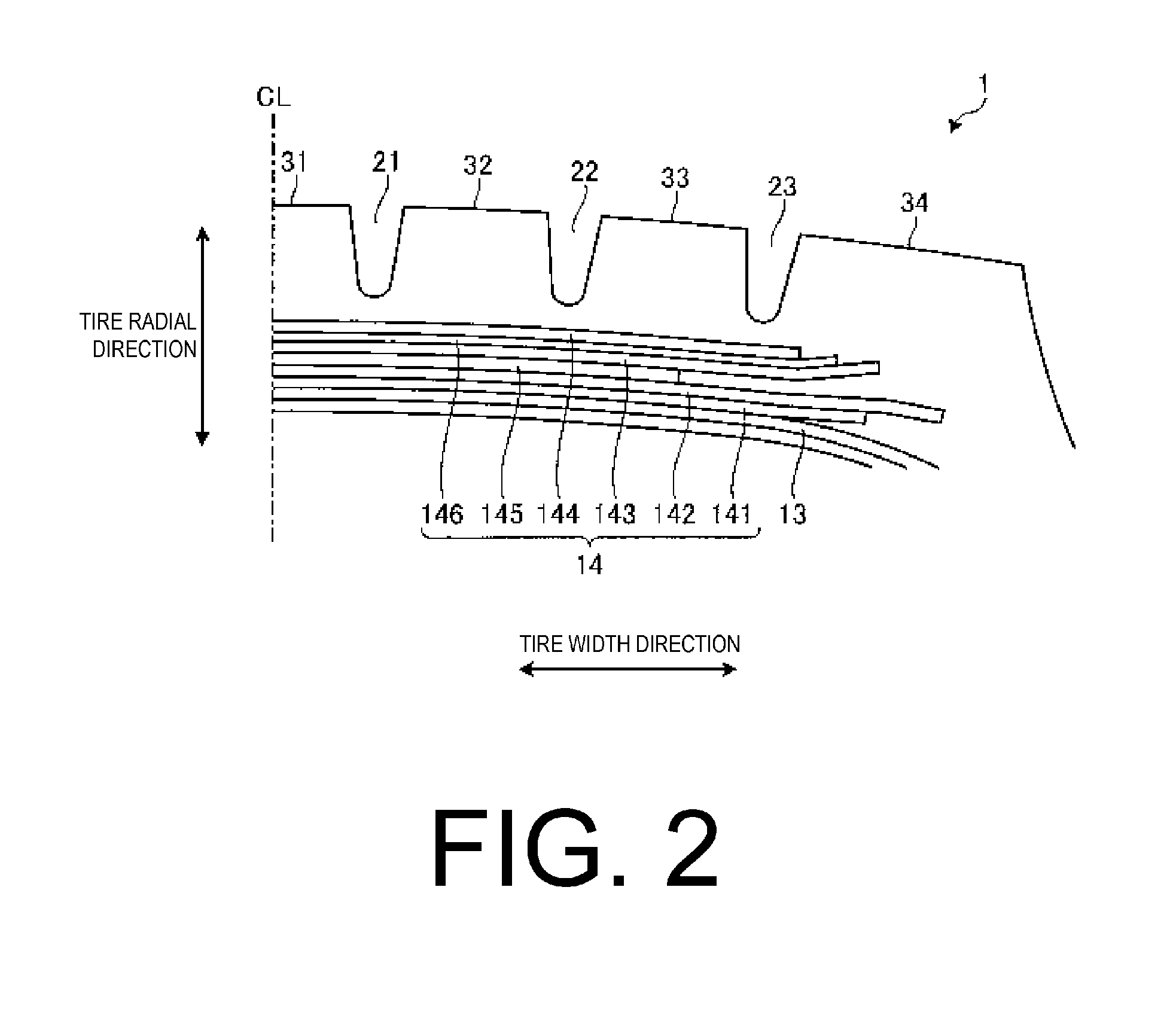
[0070]FIGS. 6 to 9 are explanatory views illustrating modified examples of the belt layer depicted in FIG. 4. These drawings schematically illustrate the arrangement of the belt cords that constitute each of the belt plies 141 to 145. In these modified examples, the same constituents as the configuration illustrated in FIG. 4 are given the same reference numerals, and their explanations are omitted.
[0071]In the configuration in FIG. 4, the circumferential reinforcing layer 145 is disposed so as to be interposed between the pair of cross belts 142, 143. Therefore, in the region located outward in the tire radial direction from the circumferential reinforcing layer 145, two belt plies (the outer-side cross belt 143 and the belt cover 144) are disposed, and two intercord distances T1, T2 and two intercord regions A1, A2 are formed.
[0072]However, the configuration is not limited thereto, and the circumferential reinforcing layer 145 may be disposed inward in the tire radial direction fr...
application example
[0112]Also, in the pneumatic tire 1, in the state where the tire is assembled on a standard rim, the regular inner pressure is applied to the tire, and the regular load is applied, preferably the aspect ratio HW is within the ranges such that 40%≦HW≦70%. In addition, the pneumatic tire 1, as in this embodiment, is preferably used as a pneumatic tire for heavy loads, such as buses or trucks and the like. With tires having this aspect ratio HW, in particular, pneumatic tires for heavy loads such as buses, trucks and the like, the ground contact shape can easily become hourglass-shape, and the occurrence of uneven wear is significant. Therefore, by applying the configuration of the pneumatic tire 1 to a tire having this aspect ratio HW, it is possible to obtain a more significant uneven wear suppression effect.
[0113]Also, in particular, preferably the pneumatic tire 1 has a block pattern (not illustrated on the drawings). As described above, in the configuration in which the belt layer...
examples
[0114]FIGS. 10a through 11b are tables showing the results of performance testing of pneumatic tires according to the embodiment of the present invention.
[0115]In these performance tests, evaluation was carried out on several different tires for (1) heel and toe wear resistance performance, (2) block tear resistance performance, and (3) durability (see FIGS. 10a through 11b). Pneumatic tires having a tire size of 445 / 50R22.5 were assembled on a “design rim” as prescribed by TRA, and 80% of the air pressure in “Tire Load Limits at Various Cold Inflation Pressures” as prescribed by TRA, and the maximum value of “Tire Load Limits at Various Cold Inflation Pressures” were applied.
[0116](1) In the evaluation of heel and toe wear resistance performance and (2) block tear resistance performance, the pneumatic tire was mounted on a 6×4 tractor-trailer test vehicle. Then, after the test vehicle had traveled 50,000 km on a normal paved road, the tires were examined for the amount of heel and ...
PUM
 Abstract
Description
Claims
Application Information
 - R&D
- Intellectual Property
- Life Sciences
- Materials
- Tech Scout
- Unparalleled Data Quality
- Higher Quality Content
- 60% Fewer Hallucinations
Browse by: Latest US Patents, China's latest patents, Technical Efficacy Thesaurus, Application Domain, Technology Topic, Popular Technical Reports.
© 2025 PatSnap. All rights reserved.Legal|Privacy policy|Modern Slavery Act Transparency Statement|Sitemap|About US| Contact US: help@patsnap.com


