
Process for treating a liquid hydrocarbon stream

a liquid hydrocarbon and stream technology, applied in hydrocarbon oil treatment, hydrocarbon oil treatment, plural serial refining stage treatment, etc., can solve the problems of limited solvent supply, reduce the overall cost of the process, reduce the risk of solvent leakage, and reduce the effect of solvent flexibility

Active Publication Date: 2016-03-15
UOP LLC
View PDF47 Cites 0 Cited by
  • Summary
  • Abstract
  • Description
  • Claims
  • Application Information

AI Technical Summary

Benefits of technology

The patent text describes a method of reducing costs and minimizing damage to downstream units in a process by removing carbonyl sulfide upstream of an extraction zone. This approach eliminates the need for expensive downstream equipment such as a carbonyl sulfide settler and a sand filter. The method also allows for increased flexibility in solvent options and the revamping of existing units for different solvents.

Problems solved by technology

The provided solvents may be limited to particular types and can carryover to downstream units causing upsets.

Method used


Image

  • Process for treating a liquid hydrocarbon stream
  • Process for treating a liquid hydrocarbon stream
  • Process for treating a liquid hydrocarbon stream

Examples


Embodiment Construction

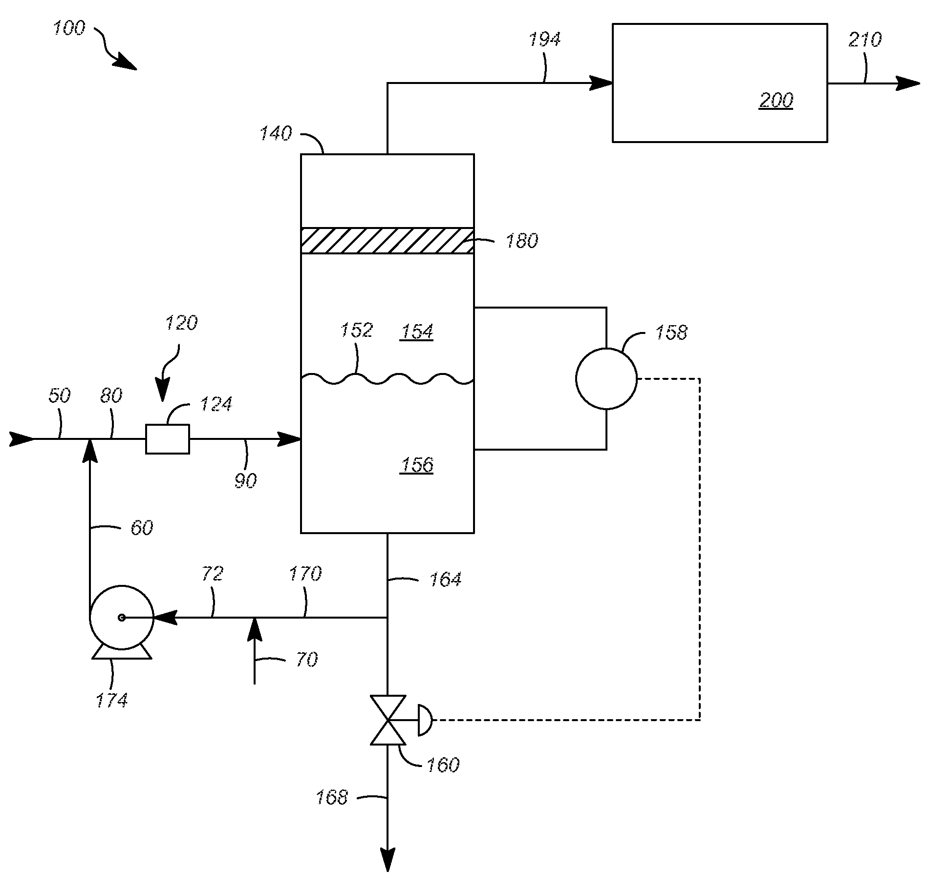
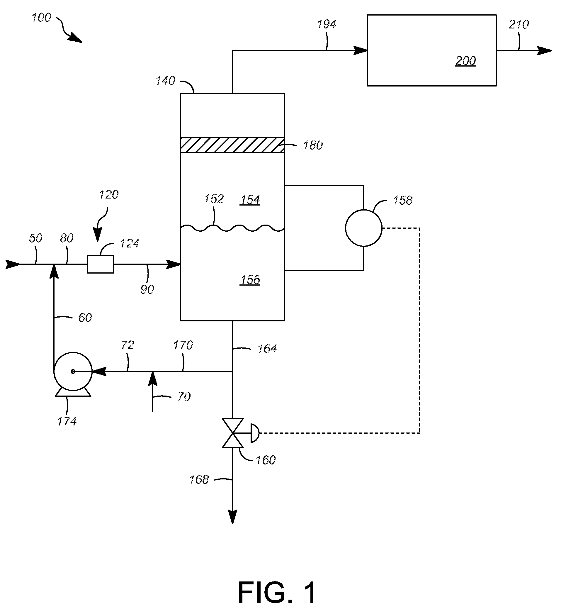
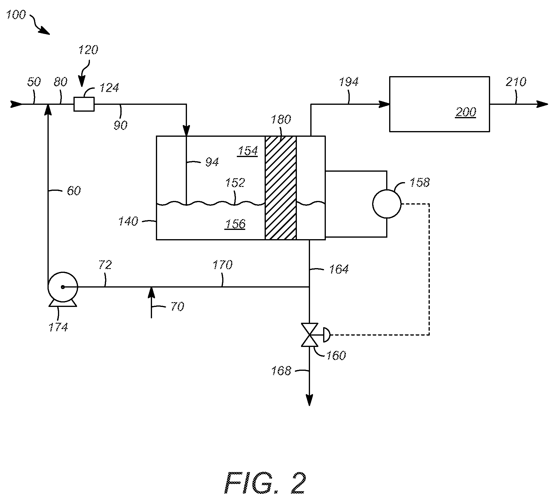
[0027]Referring to FIG. 1, an apparatus 100 can include a contacting zone 120, a vessel 140, such as a prewash vessel 140, and an extraction zone 200. A liquid hydrocarbon stream 50, such as a liquefied petroleum gas, a naphtha, or a kerosene, containing one or more sulfur compounds, such as one or more thiol compounds or hydrogen sulfide, may be provided to the apparatus 100. Usually, the liquid hydrocarbon stream 50 can be rich or substantially include one or more C1-C15 hydrocarbons, and can be substantially in a liquid phase. The liquid hydrocarbon stream 50 may also contain about 50-about 500 ppm, by weight, carbonyl sulfide and be combined with a solvent or recycle stream 60, as hereinafter described, to form a combined stream 80 before entering the contacting zone 120.

[0028]The contacting zone 120 can include any suitable device, such as a jet educator mixer, a structured column packing, a random packing, a sieve tray, and / or a static mixer. In this exemplary embodiment, a st...


PUM

PropertyMeasurementUnit
boiling pointaaaaaaaaaa

Abstract

One exemplary embodiment can be a process for treating a liquid hydrocarbon stream. The process can include passing the liquid hydrocarbon stream previously contacted with a solvent having an alkanolamine consisting of diethanolamine, a methyl diethanolamine, or a mixture thereof, and an alkali to a vessel. Generally, the vessel contains a coalescing zone for removing at least one of hydrogen sulfide and carbonyl sulfide.

Description

FIELD OF THE INVENTION[0001]This invention generally relates to a process for treating a liquid hydrocarbon stream.DESCRIPTION OF THE RELATED ART[0002]Often, hydrocarbon streams are treated to remove sulfur-containing compounds, such as mercaptans. Generally, mercaptans are removed because of their malodorous scent. Additionally, it is usually desirable to remove other compounds, such as carbonyl sulfide. As such, additional equipment may be utilized to remove these other compounds. Such equipment may be provided solvents for removing these compounds. The provided solvents may be limited to particular types and can carryover to downstream units causing upsets. It would be preferable to overcome such shortcomings by reducing the number of equipment pieces, minimize upsets of downstream units, and provide more flexibility with respect to solvents. Thus, improving operability and efficiency of such processes is desirable.SUMMARY OF THE INVENTION[0003]One exemplary embodiment can be a p...

Claims


Application Information

Patent Timeline
Patent Type & Authority Patents(United States)
IPC IPC(8): C10G19/02C10G21/27C10G53/14
CPCC10G19/02C10G21/27C10G53/14C10G2300/202
Inventor LARICCHIA, LUIGITRUCKO, JESSY E.
Owner UOP LLC
Learn More