
Adaptable socket system, method, and kit

a socket and adaptable technology, applied in the field of prosthetic limbs, can solve the problems of loss of motion between the socket wall and the underlying skeletal structure, users of these conventional sockets are left with no choice but to accept a degree of disassociation, poorer correction, or longer rehabilitation period, so as to increase the load bearing strength of skeletal structures and increase association

Active Publication Date: 2016-03-15
ALLEY RANDALL D
View PDF44 Cites 18 Cited by
  • Summary
  • Abstract
  • Description
  • Claims
  • Application Information

AI Technical Summary

Benefits of technology

The patent describes a compression system for optimizing the fitting of a prosthesis to a patient's skeletal structure. This system applies the principles of tissue compression to minimize the loss of motion between the prosthesis and the skeletal structure without causing discomfort to the patient. The system can also be used in exoskeletal devices, where the prosthesis is not designed to replace a natural limb but to capture the lost motion of the skeletal structure, for example, to immobilize a joint or increase load bearing strength. The optimal tissue compression system allows for user adjustments and fits different users who may require the exoskeletal device at different times.

Problems solved by technology

An overlooked disadvantage of conventional sockets is the lost motion between the socket walls and the underlying skeletal structures when force is applied between the two as would occur as an amputee tries to move the prosthesis as a whole.
Thus, users of these conventional sockets are left with no choice but to accept a degree of disassociation between the physical movements of the body part in the socket and the resulting movement of the socket and attached prosthetic.
In the case of orthotics or orthopedics, this disadvantage can lead to re-injury, poorer correction, or longer periods for successful rehabilitation.

Method used


Image

  • Adaptable socket system, method, and kit
  • Adaptable socket system, method, and kit
  • Adaptable socket system, method, and kit

Examples


Embodiment Construction

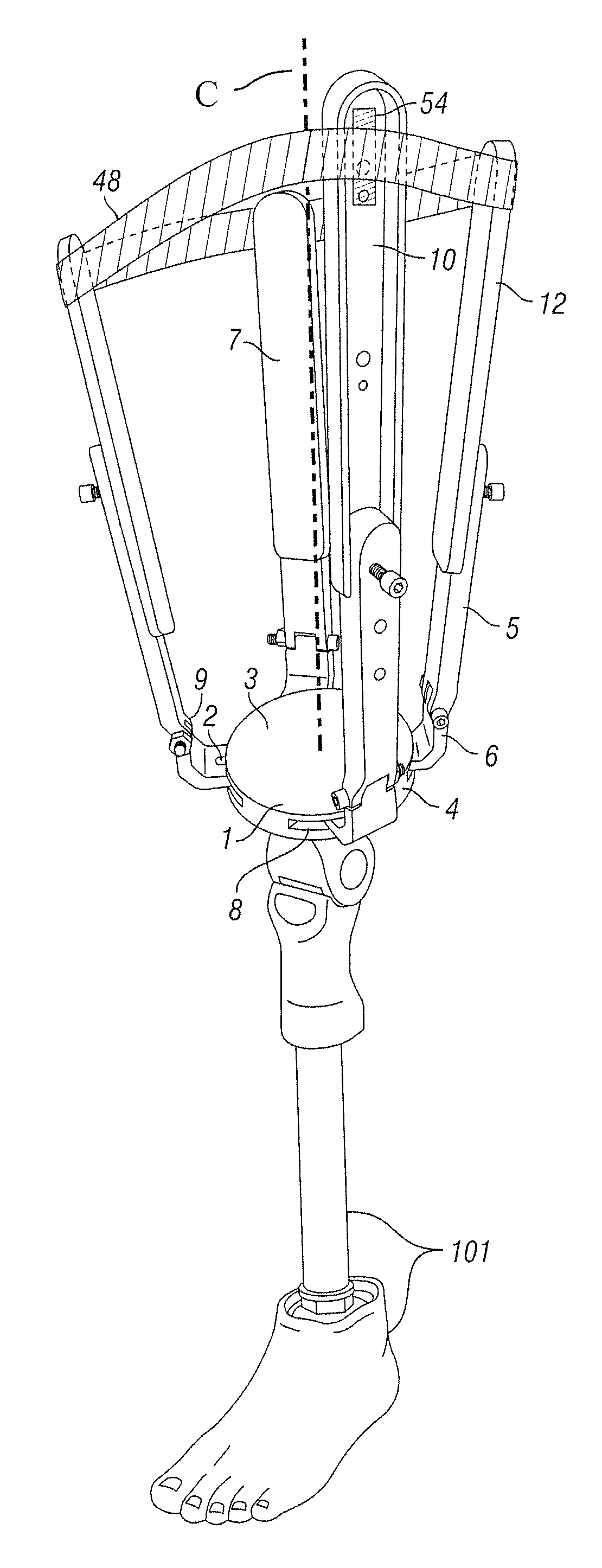
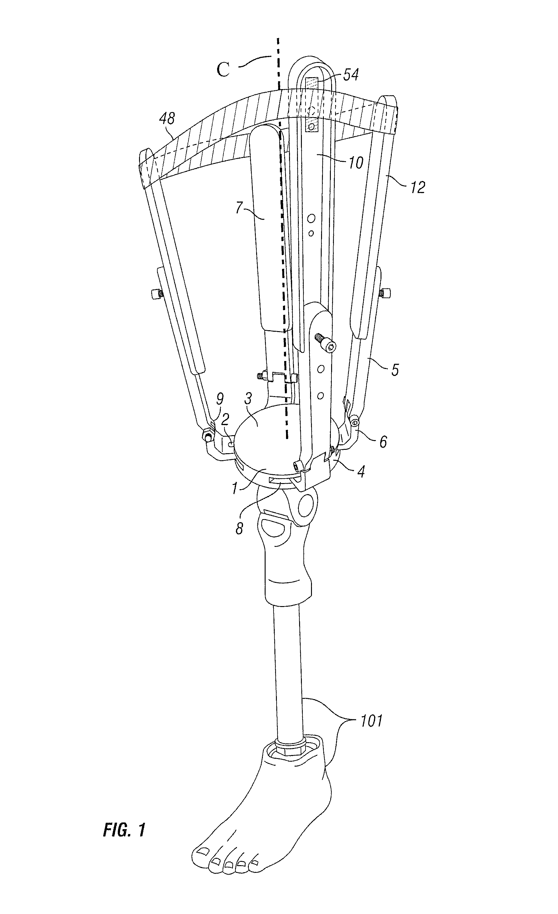
[0072]FIG. 1 depicts one embodiment that includes a prosthetic device 101 and the attached RAS compressing device and paddles. The RAS compressing device and paddles include an adapter 1 with attachment points 2 arranged azimuthally around the adapter such that the attachments are aligned at distinct intervals around the circumference of the adapter, wherein the locations of these attachment points are determined with reference to the skeletal structure of the target area, as well as by the shape and size of the target. In one variation, the adapter has four attachment points. When the target is a human limb having a skeletal structure lying within the limb these attachment points are, for example, approximately ninety degrees apart.

[0073]The adapter 1 has an inner adapter surface 3 facing the target, an outer adapter surface (not shown) opposite the inner adapter surface, and side 4 connecting the inner adapter surface to the outer adapter surface.

[0074]In one variation of this emb...


PUM


Abstract

An adjustable socket system, method, and kit for use with prosthetic devices or orthotic, orthopedic, or exoskeletal support devices that includes a paddle and a compressing device coupled to the paddle. The paddle is chosen from a plurality of paddles of different shapes in such a way that the paddle inner surface is substantially coextensive with a soft tissue area overlying skeletal structures. The compressing device presses the paddle against the soft tissue area in order to minimize the motion of the paddle relative to the underlying skeletal structures without causing discomfort to the user or compressing areas not in contact with the paddle, allowing compressed tissue to flow into uncompressed areas. The system, method, and kit can include an external tool, sensors, actuators, and controllers, to assist fitting and for adjustment after fitting. A stabilizer can be added to resist the bending force on the paddle.

Description

CROSS REFERENCE TO RELATED APPLICATIONS[0001]This application claims the benefit of priority from U.S. Provisional Patent Application No. 61 / 732,493, filed Dec. 3, 2012, and U.S. Provisional Patent Application No. 61 / 720,934, filed Oct. 31, 2012, both of which applications are incorporated in their entirety by reference herein.FIELD OF THE INVENTION[0002]The present invention relates to the prosthetic limbs worn by upper or lower limb human or animal amputees and in particular, to the portions of limb prostheses that are in direct contact with the user's limb. It also relates to orthotic support devices applied and worn to support or supplement weakened or abnormal joints or limbs. It also relates to immobilizing injured skeletal structures and associated muscles, joints, and ligaments, for example, using orthopedic support devices in the field of orthopedics. Finally, it relates to the human or animal interface component of exoskeletal support devices and associated machines, or sy...

Claims


Application Information

Patent Timeline
Patent Type & Authority Patents(United States)
IPC IPC(8): A61F2/80A61F2/70A61F2/78A61F2/76A61F2/50A61F5/01
CPCA61F2/80A61F2/70A61F2/76A61F2/78A61F5/0102A61F2002/509A61F2002/5016A61F2002/5026A61F2002/5027A61F2002/5052A61F2002/5083A61F2002/764A61F2002/7635A61F2002/7675A61F2002/802
Inventor ALLEY, RANDALL, D.
Owner ALLEY RANDALL D
Learn More