Vapor purging octane separation system

a technology of octane separation and vapor purging, which is applied in the direction of electric control, machines/engines, mechanical equipment, etc., can solve the problems of increased energy consumption, less efficient engine operation, and difficulty in controlling the air-fuel ratio of engines with such a system, so as to improve engine operation, reduce engine air-fuel ratio disturbances, and improve engine air-fuel ratio control

Active Publication Date: 2016-03-08
FORD GLOBAL TECH LLC
View PDF49 Cites 2 Cited by
  • Summary
  • Abstract
  • Description
  • Claims
  • Application Information

AI Technical Summary

Benefits of technology

[0003]It also has been proposed to separate fuels that have been combined into a single fuel mixture for the purpose of improving vehicle performance and fuel economy. One fuel mixture that may be separated into its individual component fuels is a gasoline\ethanol fuel mixture such as E10 (90% gasoline and 10% ethanol), E20, or E85. Furthermore, gasoline may be separated into a low-octane component gasoline and a high-octane component gasoline on board the vehicle. The separated fuels or fuel components may be stored in separate fuel tanks on board the vehicle.
[0006]In one example described herein, the inventors have provided control over multiple vapor purge flows into the engine from multiple fuel vapor storage devices that are in fluidic communication with a respective, but equal number of multiple fuel tanks; each of the multiple fuel vapor purge flows are controlled to be in a same proportion of total fuel vapors purged as the proportion of liquid fuel of the total liquid fuels supplied from the respective fuel tanks to the engine. This novel type of control allows the unique properties of each fuel to be fully utilized, both as a liquid and as a vapor. For example, the high-octane vapor phase fuel may be purged into the engine in proportion to the high-octane liquid phase fuel currently being injected into the engine. Otherwise, by mixing vapors from each fuel tank together in a single canister, as shown in prior approaches, the advantage of the high-octane vapor phase fuel may not be realized. Additionally, by purging fuel vapors proportionate to use of similar liquid phase fuel, engine air-fuel ratio disturbances may be reduced since the overall stoichiometric fuel ratio remains constant. In this way, fuel properties may be leveraged to benefit engine operation. Further, engine air-fuel ratio control during fuel vapor purging of multiple fuel types may be improved.
[0007]The present description may provide several advantages. In particular, the approach may allow stored fuel vapors to be used to improve engine operation in a similar way that one liquid fuel may be used to improve engine performance over a different liquid fuel. Further, the approach may improve engine air-fuel ratio control by allowing a stoichiometric air-fuel ratio to remain constant. Further still, the approach may reduce the possibility of separated fuels from being reabsorbed into fuel having different properties.

Problems solved by technology

However, it may be more difficult to control an engine air-fuel ratio with such a system since a wider range of fuel vapors may be stored in the fuel vapor storage canister because of differences between fuels stored in the multiple fuel tanks.
If re-absorption were to occur, re-separating fuel from the fuel tanks may result in increased energy consumption, or the engine may be operated less efficiently to use the combined fuel that includes fuel from different fuel tanks.
Further still, the approach may reduce the possibility of separated fuels from being reabsorbed into fuel having different properties.

Method used


Image

  • Vapor purging octane separation system
  • Vapor purging octane separation system
  • Vapor purging octane separation system

Examples


Embodiment Construction

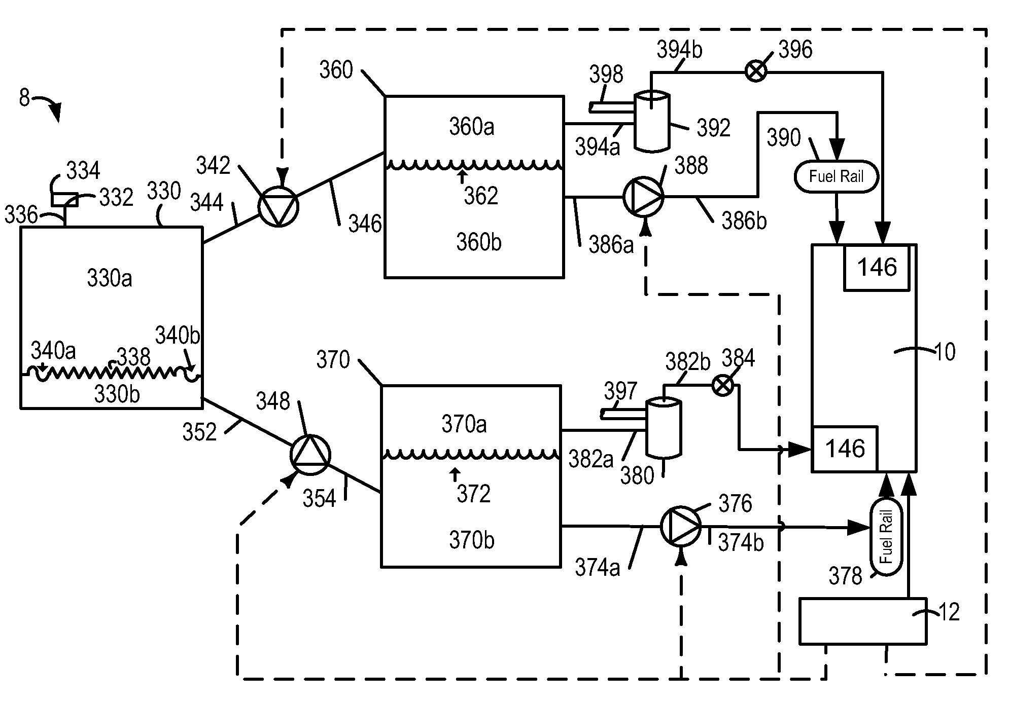
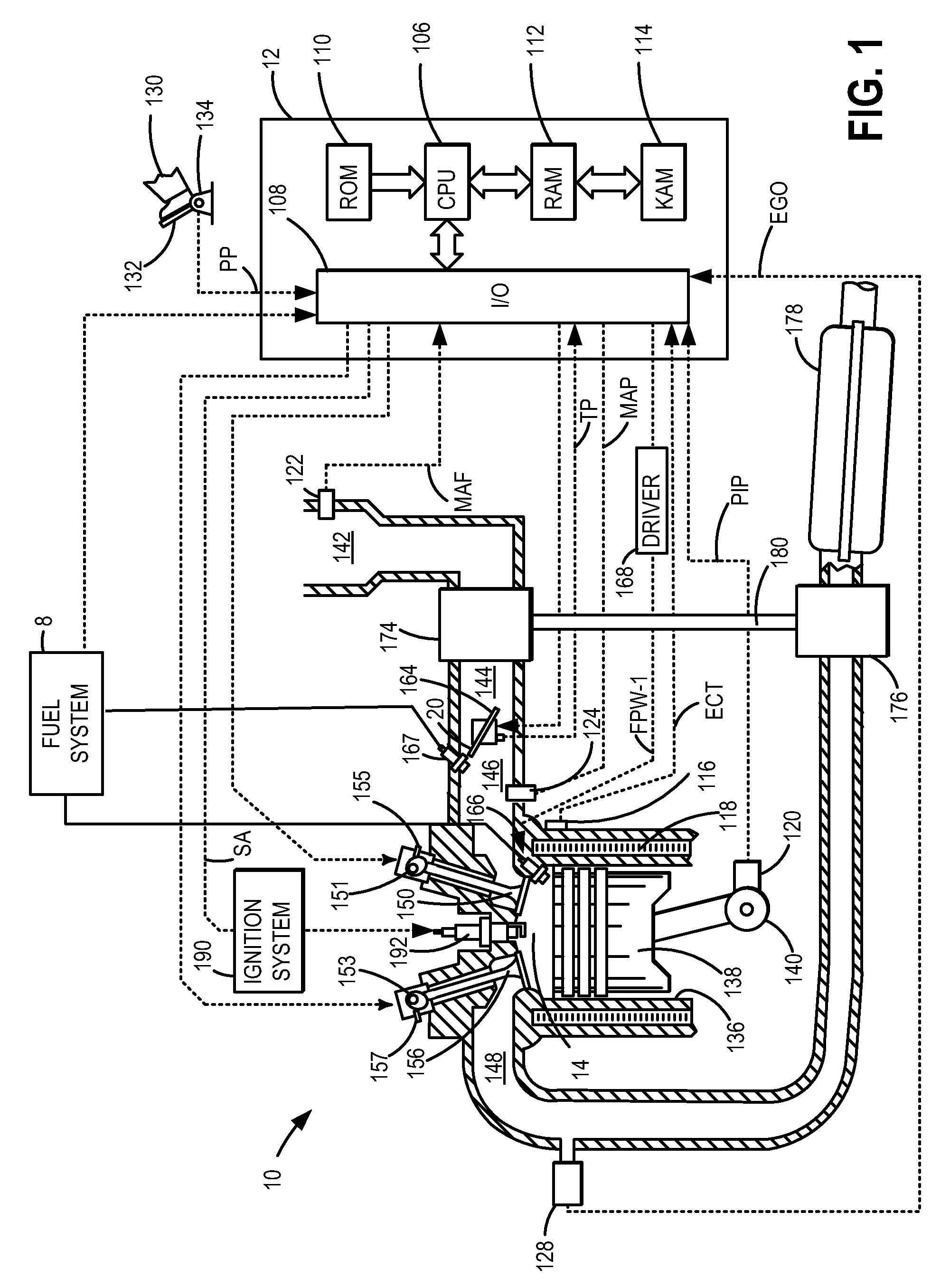
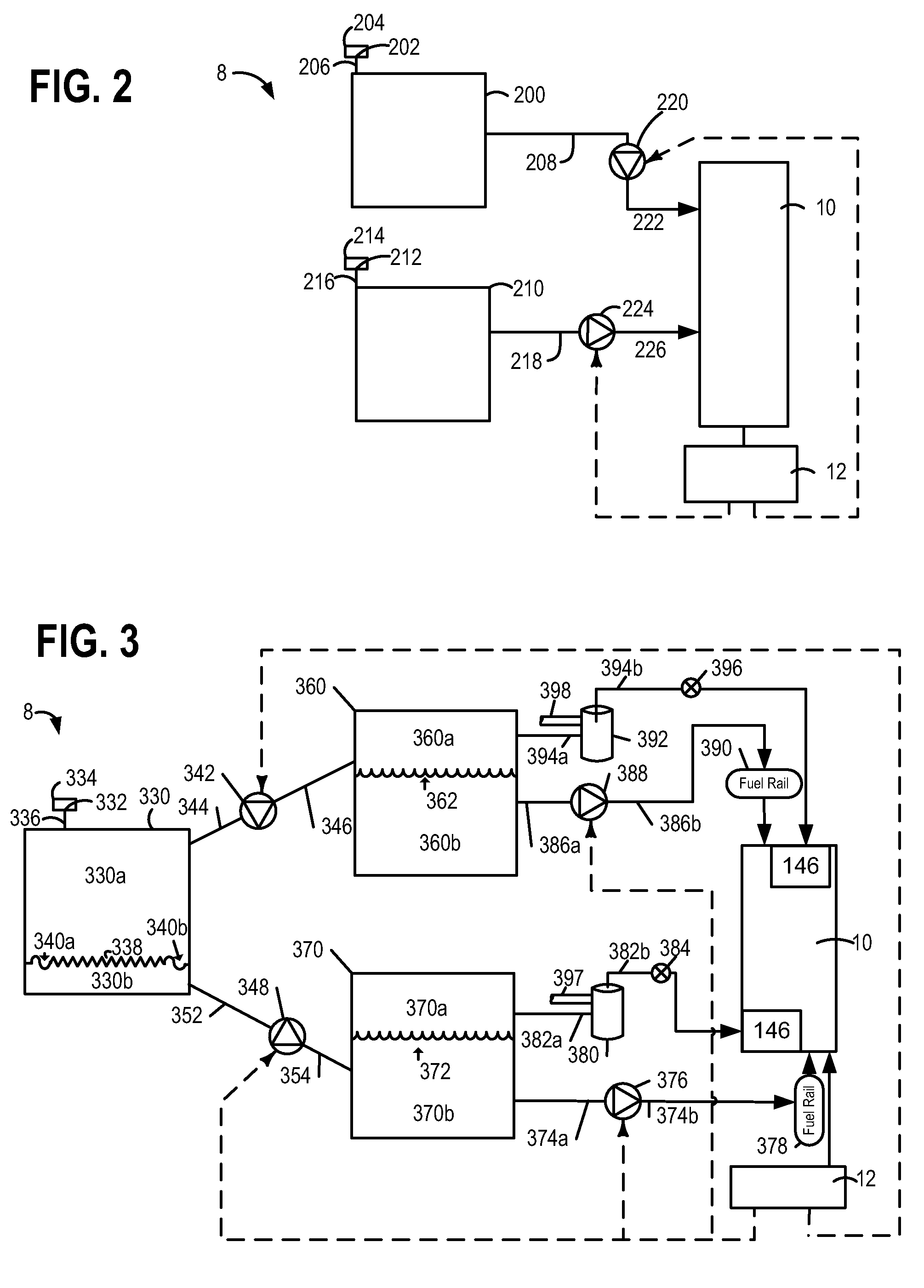
[0014]The following description relates to systems and methods of improving fuel usage in engines containing multiple fuel tanks. Because fuels may be separated into multiple fuel tanks based on different properties, fuels may be utilized most effectively in an internal combustion engine, such as the one illustrated in FIG. 1. FIGS. 2-3 illustrate example multiple fuel systems. The multiple fuel systems may provide for separating different types of fuels from fuel mixtures, and fuel vapors from different fuels may be stored in individual fuel canisters. Fuel vapors stored in canisters may be purged from the canisters to an engine in a way that utilizes each fuel's unique properties. FIG. 4 shows a method for purging different fuels stored in different storage canisters. Additionally, the method for purging fuel vapor storage canisters accounts for conditions where engine knock may be present. FIG. 5 illustrates closed-loop fuel control including purging different types of fuel vapor...


PUM


Abstract

A method for controlling an engine supplied with multiple fuels in which the vapor purge flow into the engine from multiple vapor storage devices each coupled to a respective, but equal number of multiple fuel tanks controlled to have the same proportion of total vapors purged as a proportion of liquid fuel delivered to the engine from said respective one of the said multiple fuel tanks. The method includes increasing the delivery of fuel from one of the multiple fuel tanks containing fuel with the highest-octane rating of all the fuel tanks when the vapor storage canister coupled to the fuel tank with the highest-octane fuel is not being purged of its fuel vapors. Additionally, the method further comprises a feedback control responsive to an exhaust gas oxygen sensor to adjust said fuel delivered from said multiple fuel tanks to the engine to maintain engine air-fuel ratio around stoichiometry.

Description

FIELD[0001]The field of the disclosure relates to fuel vapor storage and vapor purge control for a vehicle.BACKGROUND AND SUMMARY[0002]Engines that operate on multiple fuels are being developed. The engines may operate on mixtures including gasoline / ethanol, gasoline / compressed natural gas (CNG), diesel / gasoline, or diesel / ethanol. Each of these fuels may be stored in a separate fuel tank on board a vehicle.[0003]It also has been proposed to separate fuels that have been combined into a single fuel mixture for the purpose of improving vehicle performance and fuel economy. One fuel mixture that may be separated into its individual component fuels is a gasoline\ethanol fuel mixture such as E10 (90% gasoline and 10% ethanol), E20, or E85. Furthermore, gasoline may be separated into a low-octane component gasoline and a high-octane component gasoline on board the vehicle. The separated fuels or fuel components may be stored in separate fuel tanks on board the vehicle.[0004]U.S. Patent A...

Claims


Application Information

Patent Timeline
Patent Type & Authority Patents(United States)
IPC IPC(8): F02D19/08F02D41/00F02D41/14F02D37/02F02P5/152F02M25/08F02D35/02F02D41/38
CPCF02D19/084F02D19/08F02D37/02F02D41/0025F02D41/0032F02D41/0042F02D41/1456F02P5/152F02D19/087F02D35/027F02D2041/3881F02D2200/0611F02M25/0854F02D19/0649F02D19/0671Y02T10/30Y02T10/40
Inventor LEONE, THOMAS G.ANDERSON, JAMES ERIC
Owner FORD GLOBAL TECH LLC
Why Eureka
Try Eureka