Apparatus for spacecraft

a spacecraft and apparatus technology, applied in the field of spacecraft protection, can solve the problems of small population of trackable objects in earth orbit (including debris), rapid tumble of satellites, and rare dramatic events, and achieve the effect of improving spacecra

Active Publication Date: 2016-03-08
PHS SPACE
View PDF23 Cites 1 Cited by
  • Summary
  • Abstract
  • Description
  • Claims
  • Application Information

AI Technical Summary

Benefits of technology

[0033]Multiple shielding layers are pivotally connected to each other and to driving means such that they may be unfolded by the driving means to a third position whereby the surface area of the shield unit is further increased to provide increased atmospheric drag. In this way the multilayer debris shield has dual and triple functionality, whereby when the spacecraft mission is complete, the debris shield can be unfolded to become a de-orbit device.
[0034]Advantageously, the multiple layers of the shield are pivotally connected so that they may be unfurled to increase the effective surface area of the spacecraft and create drag. The second advantageous effect of the large surface area is that the unfurled panels can be used to sweep debris from the space environment. By combining such multiple functionalities into a single apparatus, weight overhead is reduced and shielding protection may be increased.
[0037]The configuration and orientation of the shielding layers in the third position may be such that the spacecraft enters into a stable tumbling or spinning motion such that the surface area of the layers facing a given direction is maximised.
[0038]The configuration and orientation of the shielding layers in the third position may be such that the surface area of the layers facing the direction of motion is maximised in order to maximise atmospheric drag, or the configuration and orientation of the shielding layers in the third position may be such that the surface area of the layers facing the direction of maximum incoming debris flux is maximised. The configuration and orientation of the shielding layers in the third position may be such that the surface area of the layers facing both the direction of motion and the direction of incoming debris flux is optimised in order to maximise both atmospheric drag and interaction with the debris flux.
[0044]The panels of the de-orbiting apparatus may be fabricated from a shielding material and therefore have a shielding effect on the spacecraft while in the first stowed position. The panels may be moved to an intermediate position where the panels are layered and are oriented at an angle to the spacecraft surface to which they are attached. The panels in the second unfolded position may sweep debris from the space environment.

Problems solved by technology

The collision severed a gravity gradient stabilisation boom causing the satellite to tumble rapidly.
Fortunately, such dramatic events are rare as the population of trackable objects in Earth orbit (including debris) is still relatively small (i.e. around 15,000 catalog objects as of July 2009).
However, the same is not true of smaller, non-trackable debris.
Examinations of the surfaces of manned spacecraft, such as the Space Shuttle and International Space Station (ISS), and unmanned spacecraft, such as EURECA, LDEF and the Hubble Space Telescope (HST), have revealed a wide variety of impact damage.
The damage from a 1 cm particle can penetrate deep inside an unmanned spacecraft causing extensive internal damage and potential loss of mission.
Even the special purpose multi-layer shields on a manned spacecraft are only just capable of protecting against a 1 cm particle.
A 10 cm debris impactor would most likely cause the destruction of a spacecraft.
While such improvements are useful, even with this type of enhancement, the probability of failure of a spacecraft can still be quite significant (several percent).
These shields are bulky and have a high weight overhead and in general are only used on manned spacecraft.
The risk of losing a manned mission warrants the provision of extensive shielding.
Currently, there are very few spacecraft that carry astronauts.
A problem on unmanned spacecraft is to balance the risk of losing the mission to space debris versus the cost, in terms of weight, of providing a high level of shielding.
Unfortunately, these altitudes are also the most heavily populated with orbital debris.
Predictions of the long-term growth of the debris population in these valuable regions indicate that routine spacecraft operations may soon no longer be possible because of the collision hazards.
However, creating a large surface area presents a problem in terms of weight overhead, which must be kept to a minimum for cost reasons.
A disadvantage of these systems is that it is very costly to provide a dedicated sweeping vehicle.

Method used


Image

  • Apparatus for spacecraft
  • Apparatus for spacecraft
  • Apparatus for spacecraft

Examples


Embodiment Construction

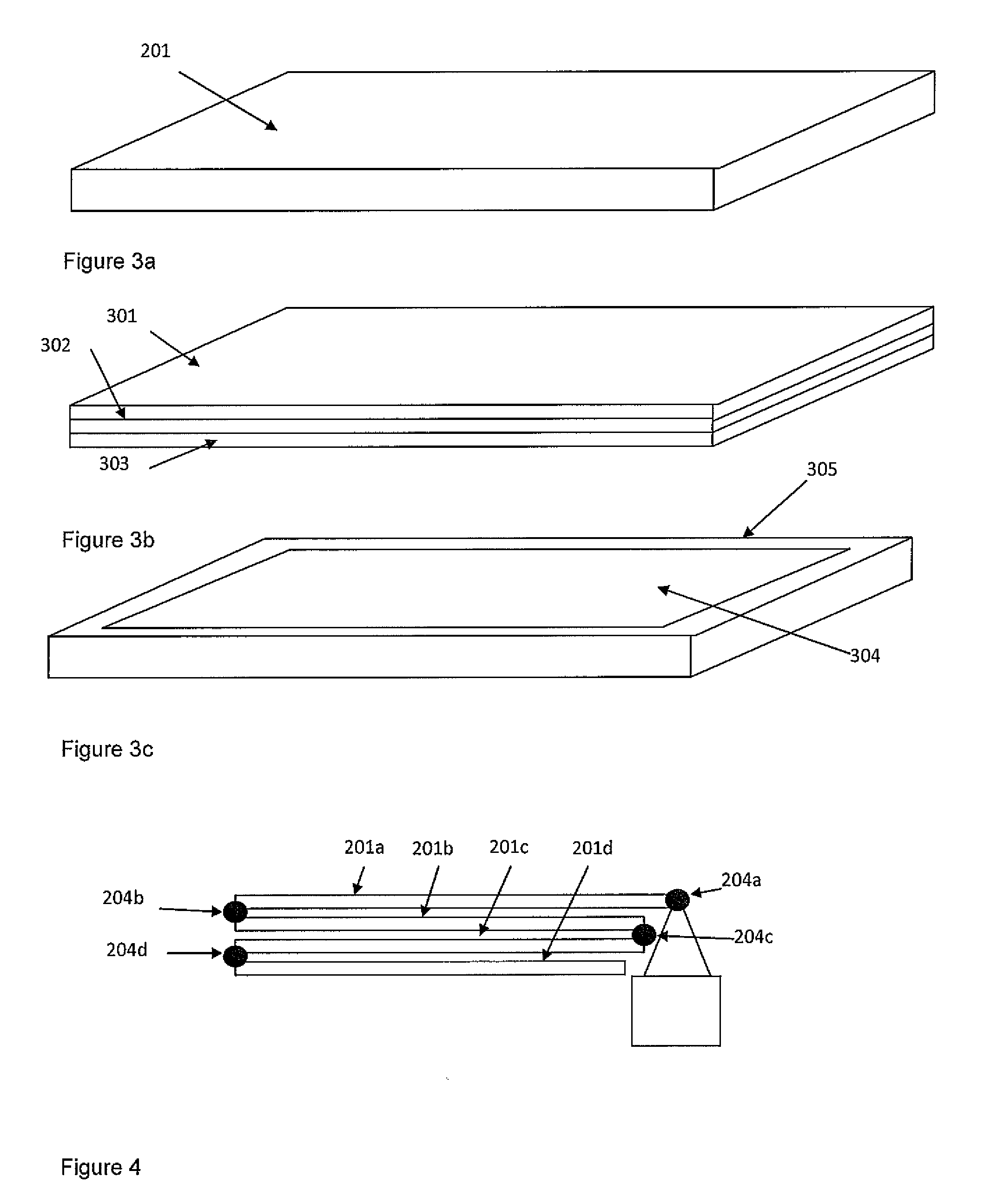
[0068]The teachings herein provide a deployable multi-functional device that can provide spacecraft with a combination of the following functions: i) shielding against impacts from space debris and meteoroids, ii) in-situ detection of space debris and meteoroid impacts, iii) end-of-life deorbiting for spacecraft in LEO, iv) removal of small size debris from the space environment by acting as a ‘sweeper’.

[0069]The shielding configuration provides an order of magnitude improvement in impact protection for a typical LEO spacecraft in a cost-effective manner. Impact detectors provide data for monitoring of the space debris environment, thus increasing knowledge for debris environment modellers, providing real-time information for spacecraft operators, and raising awareness of the problem of debris impacts. The ability to increase the surface area of the spacecraft assists end of life spacecraft deorbiting in LEO, thus providing benefits such as propellant-saving, increased mission reven...


PUM


Abstract

The invention relates to the protection of spacecraft from debris and to de-orbiting devices of the atmospheric drag type, and to debris sweeping apparatus for the removal of debris from the space environment. The debris shielding apparatus for a spacecraft has a shield unit including a shielding surface for impeding incident debris. The shield unit is attached to the spacecraft body and has a drive mechanism for positioning the shield unit in relation to the spacecraft body. The drive mechanism is capable of moving the shield unit between a stowed first position and a deployed second position. In the deployed second position the plane of the shielding surface is at an angle to the spacecraft body.

Description

CROSS REFERENCE TO RELATED APPLICATIONS[0001]This application is a National Stage application of International Application No. PCT / GB2010 / 052037, filed Dec. 7, 2010, the subject matter of which is incorporated by reference in its entirety.BACKGROUND[0002]1. Technical Field of the Invention[0003]The invention relates to the protection of spacecraft from debris, in the preferred embodiment to the provision of shielding structures and for monitoring space debris impacts on the shielding structures. The invention also relates to the field of de-orbiting devices, in the preferred embodiment of the atmospheric drag type. The invention also relates to debris sweeping apparatus preferably for the removal of debris from the space environment.[0004]2. Description of Related Art[0005]A typical spacecraft in low Earth orbit (LEO) can have a through-life impact-induced probability of failure of up to 5% as a result of interaction with the population of orbital debris larger than 1 mm. Set in the...

Claims


Application Information

Patent Timeline
Patent Type & Authority Patents(United States)
IPC IPC(8): B64G1/56B64G1/22B64G1/24B64G1/10
CPCB64G1/242B64G1/1078B64G1/222B64G1/56B64G1/52
Inventor STOKES, PETER, HEDLEY
Owner PHS SPACE
Why Eureka
Try Eureka