
Pinless attachment systems and methods of using the same

a technology of pinless hinges and hinge assemblies, which is applied in the direction of door/window fittings, multi-purpose tools, construction, etc., can solve the problems of low precision, low precision, and low precision of pinless hinges, and achieves the effect of reducing the risk of pin failure, and reducing the cost of forming accurately aligned and well-fitted openings for receiving pins

Inactive Publication Date: 2016-03-01
BELL JOHN RICHARD
View PDF12 Cites 2 Cited by
  • Summary
  • Abstract
  • Description
  • Claims
  • Application Information

AI Technical Summary

Benefits of technology

The invention is a pivot channel member that can be easily attached to a pivot bar. It is designed in a way that allows heavy objects to be easily secured without needing to see the attachment during installation. The installation process involves only a few steps and allows for flexibility in positioning and attaching objects. The structure can be locked in place to ensure stability. The technical effects of this invention include simplifying the installation process and allowing for easy attachment of heavy objects.

Problems solved by technology

There are a number of disadvantages associated with the “standard” pin-type or three-piece hinge.
These include the relatively high cost of forming accurately aligned and well-fitted openings for receiving the pin, susceptibility to malfunction from dirt or corrosion, and the fact that the pin itself may be broken, displaced or lost altogether.
A further disadvantage of the pin-type hinge is most readily appreciated in certain contexts, such as when one (or each) of the wing sections is attached to a large, heavy, and / or unwieldy structure.
When a conventional hinge is used for such situations, it is difficult to align the two hinge halves long enough to insert the pin.
An individual working alone with pin-type hinges may find the task of pivotably coupling such cumbersome structures to be very difficult or even impossible.
The process of detaching one structure from another can be equally laborious to an individual working alone.
One of the principal deficiencies of the Tuor arrangement is that its lower wing section, with its integral shank and transverse pivot bar structure, is complex and expensive to manufacture.
Another is that it is difficult to adapt this arrangement to the pivotable coupling of one or more cumbersome objects such, for example, as long shelves or awnings, where alignments of the respective wing sections must be achieved across much wider distances.
More substantial deficiencies reside in the fact that the hinge assembly is not self-locking (e.g., the lower wing section of Tuor may easily work loose or become dislodged out of registration with the open channel defined by the upper wing section).
For example, the McClellan structure is limited to situations in which one of the two pivotably connected structures remains disposed in a horizontal plane.
Also like Tuor, the McClellan device does not permit relative adjustment of the hinge components or associated structures once the hinge components are attached.
This is because the spacing between hinge sections secured to one structure is often so great that these sections cannot be aligned with complementary sections on the other structure without help.
Finally, the absence of an intrinsically stable locking system means that the drop leaf hinge assembly taught by McClellan cannot be safely adapted to heavier duty applications such, for example, as those where a heavily loaded ancillary structure might pull away from the primary working surface to which it is pivotably secured.
If such a structure were to drop down unexpectedly, it could seriously injure workers in the area and / or damage adjacent structures and equipment.
One disadvantage of the telescoping hinge design is that it is not adaptable to the pivotable connection of large heavy structures.
Another is the difficulty of aligning and inserting the smaller of the pivot tubes within the larger one, a problem whose magnitude increases exponentially as the length of the pivot axis increases—especially where lateral clearance and accessibility are limited.
Even where lateral access does not impose a constraint, a structure to be pivotable secured relative to another may be so long that an individual installer may be unable to keep the two pivot tubes in alignment long enough to bring them into telescoping alignment.
However, the application of extrusion processes to materials having requiring greater load bearing ability, strength, wear resistance, and other mechanical properties—may require expensive post-extrusion processes such as annealing, quenching and the like.
Common to all of the aforementioned hinge structures are susceptibility to wear and corrosion, as well as a vulnerability to accidental separation where the objects attached to each hinge section are rotated together to some degree about an axis.
Even a three-part hinge is vulnerable, in that the hinge pin can fall out when the entire hinge assembly is inverted (or subjected to centrifugal forces).

Method used


Image

  • Pinless attachment systems and methods of using the same
  • Pinless attachment systems and methods of using the same
  • Pinless attachment systems and methods of using the same

Examples


Embodiment Construction

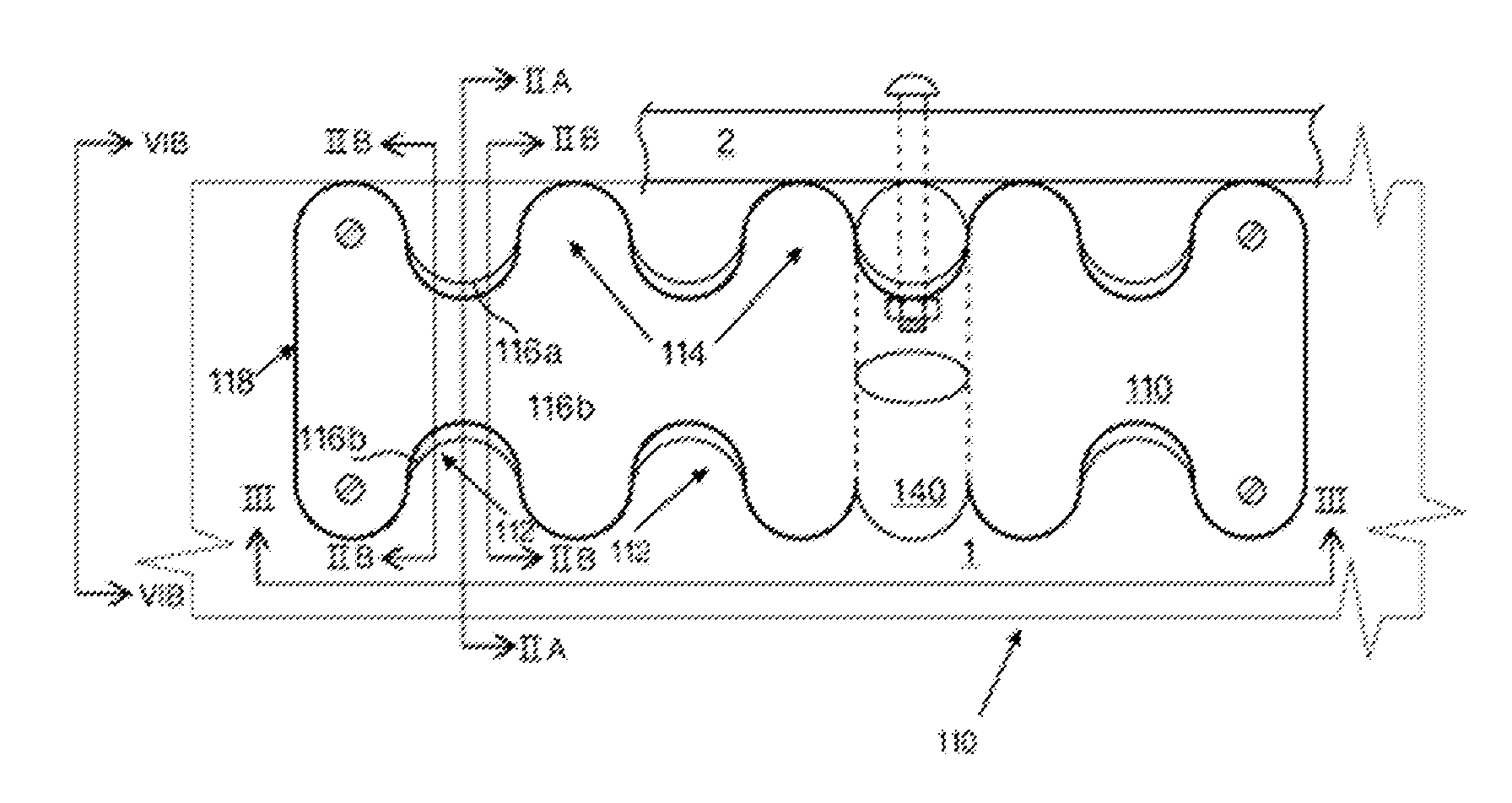
[0047]Before describing the illustrated embodiment in detail by reference to particular contexts and applications, it should be borne in mind when reviewing the drawings and accompanying description that the inventive assemblies disclosed herein have a wide variety of applications. These applications include, among others: (a) the construction of a boat moorage system which obviates the need for ropes, cleats and fenders; (b) removable access doors and hatches for boats, recreational vehicles (RVs); homes and other buildings; (c) simple awning or signage kits, for installation on a home, rented apartment, commercial building, boat or RV, which can be installed by a single individual without regard to the spacing between points of attachments; (d) attachment of tables, chairs, beds, and other furnishings in boats, RVs, student dormitories, an the like where rapid installation, removal, and rearrangement to suit individual users' needs is highly desirable; (e) quick erection of securi...


PUM

PropertyMeasurementUnit
angleaaaaaaaaaa
angleaaaaaaaaaa
widthaaaaaaaaaa

Abstract

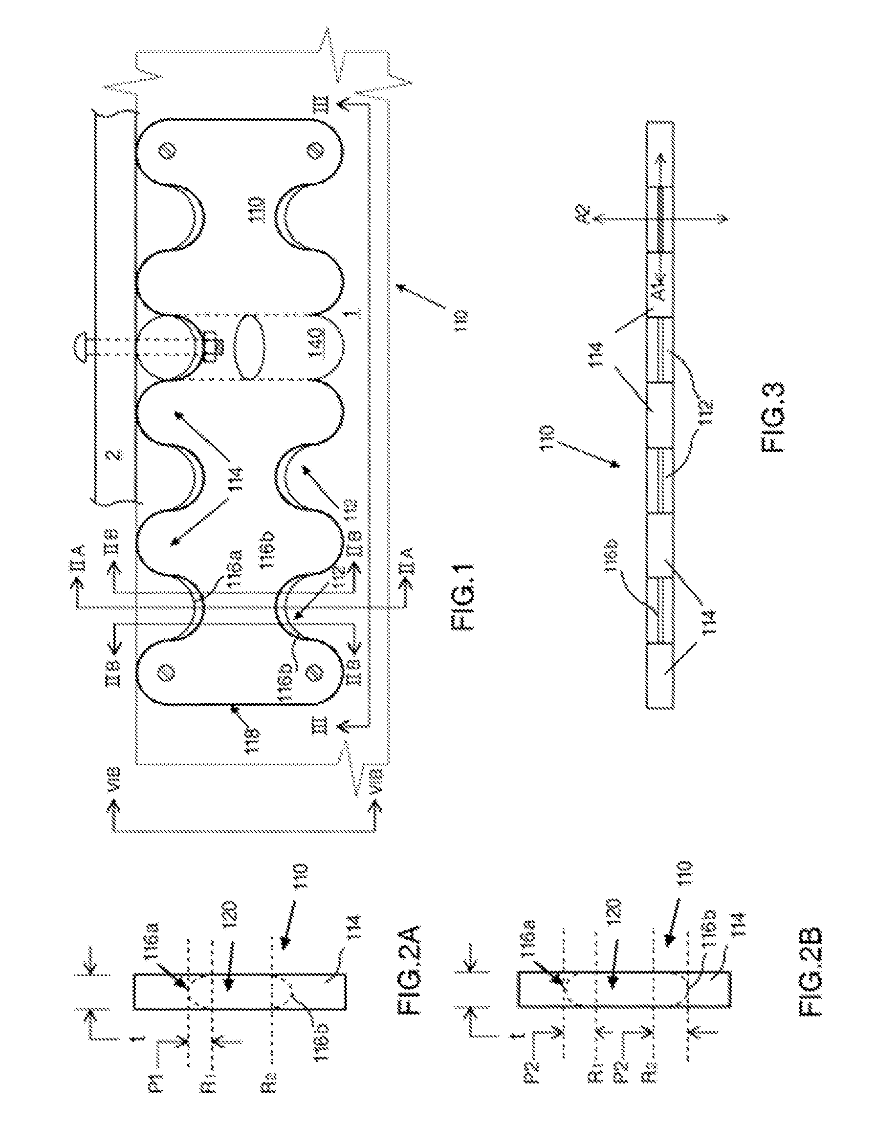
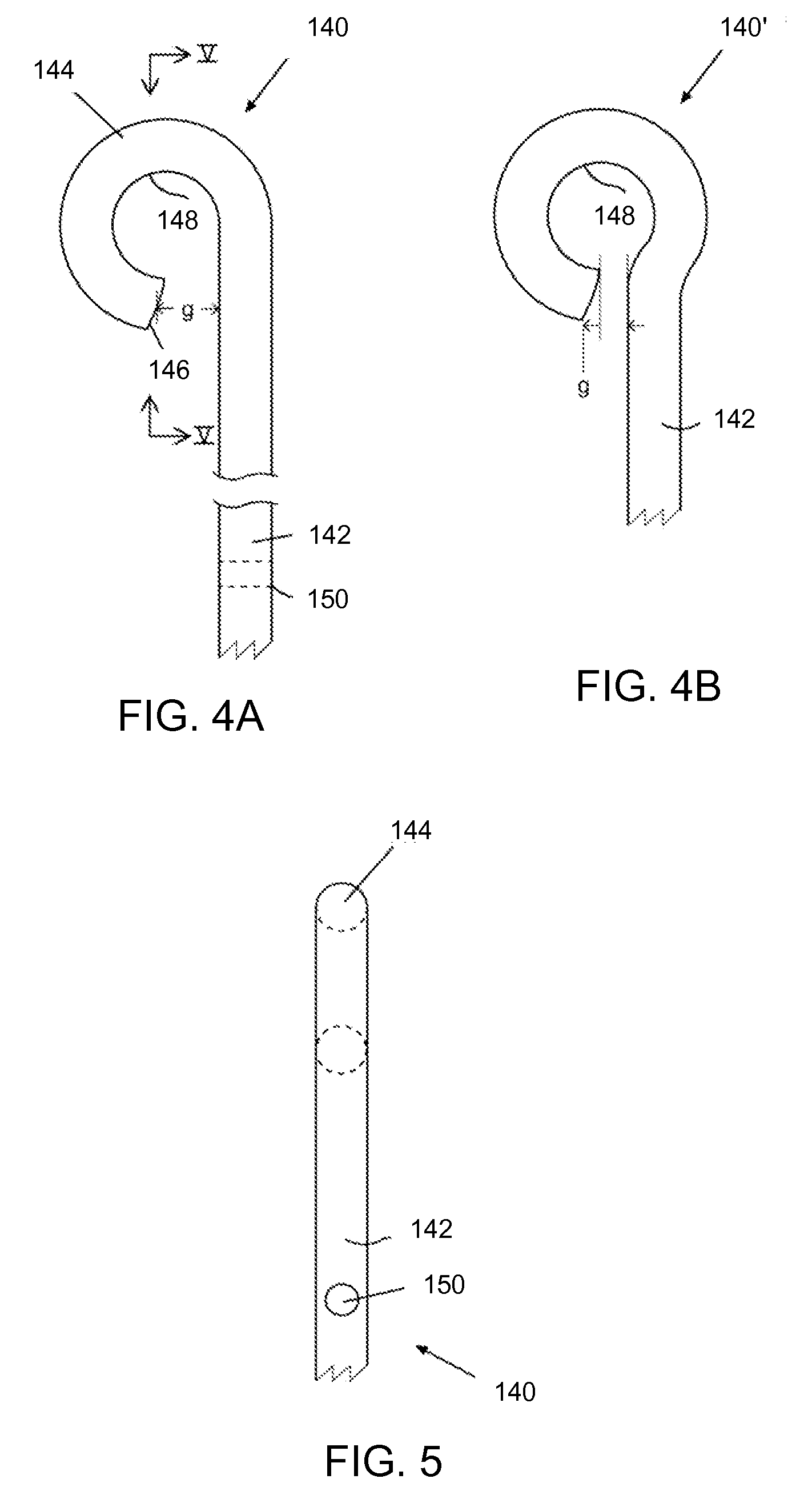
A multi-purpose pinless attachment system includes a first structure having oppositely facing recesses separated by a web region. Pairs of recesses form pivot bar bearing surfaces, and a transverse pivot axis passes through the web region at a midpoint between these pairs of bearing surfaces. A second structure defines an interior pivot channel between its distal tip and a proximal shank. The tip is separated from the shank by a gap to allow the web region of the first structure to pass through the gap while the interior pivot channel is brought into bearing registration with the pivot bar. The pivot channel receives the portion of the web region separating the first and second recesses. Surface portions of the pivot channel frictionally engage at least a portion of a pivot bar bearing surface while the second structure is pivoted relative to the first structure about the transverse pivot axis.

Description

REFERENCE TO RELATED APPLICATIONS[0001]This application claims the benefit of priority to U.S. Provisional Patent Application Ser. No. 61 / 841,095 entitled ATTACHMENT DEVICE and filed on Jun. 28, 2013.BACKGROUND OF THE INVENTION[0002]1. Field of the Invention[0003]This invention relates generally to systems and methods for enabling one structure to be attached and / or pivotably moved relative to another structure and, more particularly, to attachment assemblies of the pinless hinge type configured to both pivotably and releasably couple such structures.[0004]2. Discussion of the Background Art[0005]In its most familiar form, a hinge includes a pair of hinge halves with each hinge half including a wing section and a half channel coupled to the wing section. When the half channels of the hinge halves are aligned, the half channels form a pivot channel for receiving a separate pivoting pin. When the wing sections are attached to respective objects or structures, such as a door and a door...

Claims


Application Information

Patent Timeline
Patent Type & Authority Patents(United States)
IPC IPC(8): E05D1/04E05D7/10
CPCE05D1/04Y10T16/52Y10T29/24E05D7/1066E05Y2900/602E05Y2900/148Y10T16/535E05Y2999/00
Inventor BELL, JOHN, RICHARD
Owner BELL JOHN RICHARD
Learn More