
Apparatus for ventilation of a casting mold

a technology for ventilation apparatus and casting mold, which is applied in the direction of foundry molds, foundry cores, foundry moulding apparatus, etc., can solve the problems of increasing wear of valve bodies and relatively high cost of wear-resistant materials

Active Publication Date: 2016-03-01
KSM CASTINGS GROUP GMBH
View PDF9 Cites 1 Cited by
  • Summary
  • Abstract
  • Description
  • Claims
  • Application Information

AI Technical Summary

Benefits of technology

The invention is aimed at improving an apparatus for ventilation of a casting mold to prevent wear and produce high-quality cast parts, particularly made of aluminum and magnesium alloys. The invention provides a cost-effective solution for ventilation and prevents premature solidification of material in the ventilation channels. It also requires less maintenance and is easy to handle. Additionally, the invention can be used without a cooling device and ejector, which further reduces maintenance costs.

Problems solved by technology

Because of the high flow velocity of the casting material in the valve body, increased wear of the valve body occurs in the inflow region.
It is known to configure the valve body with wear-resistant material in the inflow region, but such wear-resistant materials are relatively expensive.

Method used


Image

  • Apparatus for ventilation of a casting mold
  • Apparatus for ventilation of a casting mold
  • Apparatus for ventilation of a casting mold

Examples


Embodiment Construction

[0051]When the same reference numbers are used in FIGS. 1 to 8, they also refer to the same parts or regions.

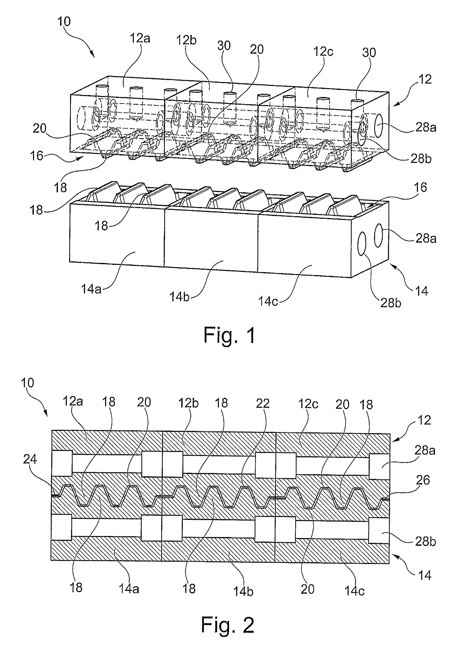
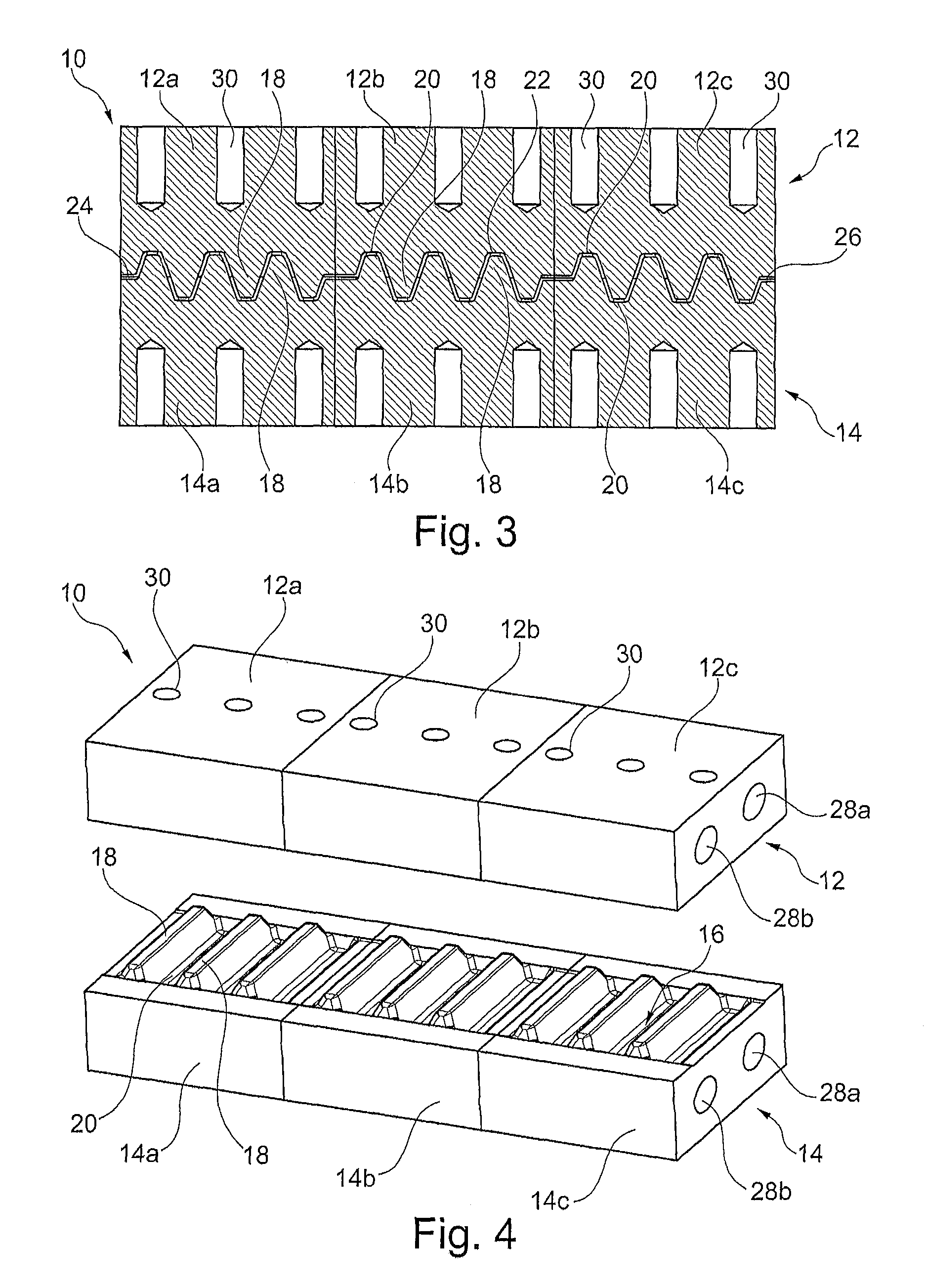
[0052]As shown in FIGS. 1 to 4, the invention relates to an apparatus 10 for ventilation of a casting mold, particularly in the form of a chill vent, having two mold halves 12, 14 that lie opposite one another and are complementary, in terms of shape and function, to one another, which halves have a plurality of elevations 18 and / or depressions 20, in each instance, which run essentially parallel to one another and essentially transverse to the flow direction, on their surfaces 16 that face one another, in such a manner that when the mold halves 12, 14 are set onto one another, a gap 22 having an inlet 24 and an outlet 26 forms between the mold halves 12, 14, at least in part, which gap can particularly be washboard-shaped, labyrinth-shaped and / or meander-shaped, and through which gap air displaced out of the casting mold and excess molten material can flow during filling of ...


PUM

PropertyMeasurementUnit
Forceaaaaaaaaaa
Shapeaaaaaaaaaa

Abstract

An apparatus for ventilation of a casting mold has two mold halves that lie opposite one another and are complementary, in terms of shape and function, to one another. The halves have a plurality of elevations and / or depressions, in each instance, which run essentially parallel to one another and essentially transverse to a flow direction, on their surfaces that face one another, in such a manner that when the mold halves are set onto one another, a gap having an inlet and an outlet forms between the mold halves, at least in part. The gap is washboard-shaped, labyrinth-shaped and / or meander-shaped. Through the gap, air displaced out of the casting mold and excess molten material flow during filling of the casting mold. At least one mold half is formed by multiple segments disposed next to one another in the longitudinal direction of the mold half and releasably attached.

Description

CROSS REFERENCE TO RELATED APPLICATIONS[0001]Applicant claims priority under 35 U.S.C. §119 of German Application No. 10 2013 100 442.3 filed on Jan. 16, 2013, the disclosure of which is incorporated by reference.BACKGROUND OF THE INVENTION[0002]1. Field of the Invention[0003]The invention relates to an apparatus for ventilation of a casting mold.[0004]2. Description of the Related Art[0005]When filling a casting mold, for example during high-pressure or low-pressure casting, during chill casting or some other casting method, the air situated in the casting mold has to be removed from the casting mold in order to achieve a clean casting result without cavities and porosities. This can either be done actively, by means of evacuation of the mold before the actual filling process, passively by means of displacement of the air during introduction of the casting material, or by means of a combination of these two methods.[0006]Apparatuses for ventilation of a casting mold in the form of ...

Claims


Application Information

Patent Timeline
IPC IPC(8): B22C9/06B22D17/14
CPCB22C9/067B22D17/145
Inventor WERNER, MICHAELSCHIRM, WOLFGANG-MICHAEL
Owner KSM CASTINGS GROUP GMBH
Learn More