Ceiling vent diffuser

a diffuser and ceiling vent technology, applied in the field of ceiling vents, can solve the problems of effectively blocking airflow at a particular workstation, relatively unaffected overall temperature of the building, etc., and achieve the effects of reducing the and reducing the overall size of the diffuser

Active Publication Date: 2016-02-02
AIRVISOR
View PDF47 Cites 2 Cited by
  • Summary
  • Abstract
  • Description
  • Claims
  • Application Information

AI Technical Summary

Benefits of technology

[0009]The device is complementary shaped to a region of the diffuser. If a typical square diffuser is viewed from the position of the mouth of the vent pipe to which the diffuser is attached, then the diffuser may be considered to have four directional quadrants out of which air flows. Those quadrants are effectively directed toward the north, the south, the east and the west. Under normal operating conditions, air radiates outwardly and downwardly from the vent and through the diffuser in all four quadrants. The device of the present invention provides a mechanism for blocking airflow in a selected one of the quadrants. When installed, the device blocks the openings in that region and substantially prevents air from flowing out of the openings. The device can be quickly and easily installed and removed and thereby allows for rapid blocking of the airflow in any one direction from the diffuser. The airflow out of the remaining three quadrants is increased proportionately, but the overall volume of air flowing out of the vent is not reduced. Consequently, the airflow at a particular workstation, for example, may be effectively blocked, but the overall temperature of the building is relatively unaffected.
[0011]In alternative embodiments of the invention, the hook member is provided with two or more engagement regions which enable it to engage vanes on different manufacturer's diffusers. The first end of the hook member is either pivotally secured to the flexible member or is engaged in an adjustment mechanism thereon. The adjustment mechanism allows the first end of the hook member to be reciprocally moved along a channel in the adjustment mechanism which then causes the second end of the hook to be situated in different positions relative to an interior edge of the flexible member. This enables the installer to install the flexible member on differently configured diffusers. An extension member is detachably engaged with the flexible member to increase the overall size thereof to accommodate larger diffusers. The extension member is easily removed to reduce the size of the diffuser. The hook member may further include a second end that is curved toward the inner surface of the flexible member and is biased toward the same.

Problems solved by technology

Consequently, the airflow at a particular workstation, for example, may be effectively blocked, but the overall temperature of the building is relatively unaffected.

Method used


Image

  • Ceiling vent diffuser
  • Ceiling vent diffuser
  • Ceiling vent diffuser

Examples


second embodiment

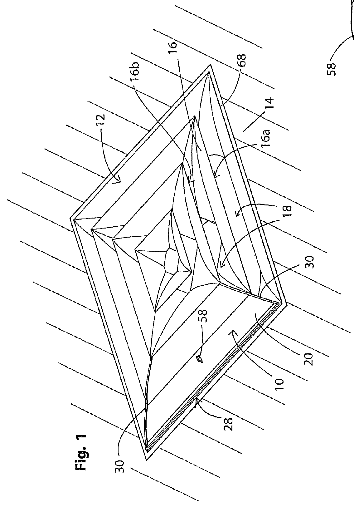
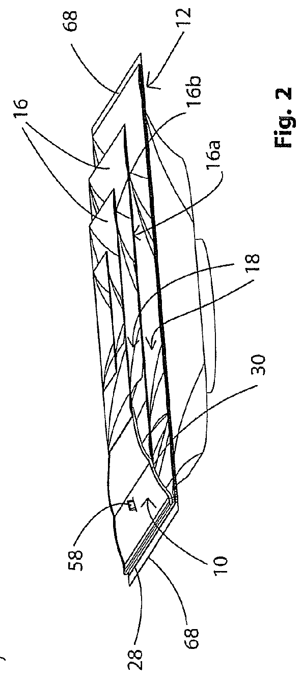
[0066]Referring to FIGS. 20-23b there is shown a vent cover in accordance with the present invention and generally indicated at 110. Vent cover 110 is substantially identical to vent cover 10 and includes a flexible member 120 positionable to be seated over an exterior surface of a vent diffuser and to thereby obstruct a region of the diffuser to substantially prevent airflow from that obstructed region. Flexible member 120 has an inner surface 122, an outer surface 124, an interior edge 126, an exterior edge 128 and side edges 130 extending between the interior and exterior edges 126, 128. Flexible member 120 tapers from exterior edge 128 to interior edge 126 and has the shape of a truncated triangle. Flexible member 120 comprises two gently curved or pillowed regions, namely first region 132 and second region 134 that meet along a shallow ridge 136. The term “pillowed” is used to describe a cross-sectional shape that is generally planar but includes a very gentle curve. This pillo...

third embodiment

[0083]Referring now to FIGS. 24-30 there is shown a vent cover in accordance with the present invention and generally indicated at 310. Cover 310 is substantially identical to cover 110 in its structure, function and method of use with the exception that cover 310 also includes an extension member 372. Vent cover 310 includes a flexible member 320 substantially identical to flexible member 220, Flexible member 320 includes an inner surface 322, an outer surface 324, an interior edge 326 an exterior edge 328 and side edges 330 extending between the interior and exterior edges 326, 328. Flexible member 320 tapers from exterior edge 328 to interior edge 326 and has the shape of a truncated triangle. Flexible member 320 comprises two gently curved or pillowed regions, namely first region 332 and second region 334 that meet along a shallow ridge 336. As best seen in FIG. 25, cover 310 further includes a lip 380 on outer surface 324 and which extends around the periphery of cover 310 and ...

fourth embodiment

[0095]Referring to FIGS. 31-35, there is shown a vent cover according to the present invention and generally indicated at 410. Cover 410 includes a flexible member 420 having the pillowed design of cover 110 and is comprised of a first region 432 and a second region 434 which join each other along a shallow ridge 436. Cover 410 is shown free of a foam strip similar to strip 142 but it will be understood that if certain manufacturer's diffusers require it, such a strip could readily be applied to exterior edge 428 thereof. As with the previously described embodiments, cover 410 also includes an interior edge 426 and opposed side edges 430, an inner surface 422 and an outer surface 424.

[0096]In accordance with a specific feature of the present invention, cover 410 includes yet another embodiment of a locking mechanism. The locking mechanism in accordance with the present invention includes one or more tabs 442 which extend outwardly from inner surface 422 of cover 410. Tabs 442 are su...


PUM


Abstract

A device for altering the airflow pattern from a ceiling vent diffuser by obstructing openings in a region of the diffuser. The device comprises a flexible member that is secured to a diffuser vane by a hook member and two tabs. The hook member has two or more engagement regions which enable it to engage vanes on different manufacturer's diffusers. The first end of the hook member is either pivotally secured to the flexible member or is engaged in an adjustment mechanism thereon. The adjustment mechanism allows the second end of the hook to be situated in different positions relative to an interior edge of the flexible member so as to accommodate different diffusers. An extension detachably engages the flexible member to increase the size thereof to accommodate larger diffusers.

Description

CROSS-REFERENCE TO RELATED APPLICATIONS[0001]This application is a Continuation-in-Part of U.S. patent application Ser. No. 12 / 062,239 filed Apr. 3, 2008, the entire specification of which is incorporated herein by reference.BACKGROUND OF THE INVENTION[0002]1. Technical Field[0003]This invention generally relates to air circulation systems for buildings. More particularly, the invention relates to ceiling vents. Specifically, the invention relates to a cover that is detachably connectable to a ceiling vent diffuser to block airflow from a region of the diffuser.[0004]2. Background Information[0005]Most industrial and commercial buildings have 24″×24″ square ceiling vent diffusers that are mounted on drywall or T-bar ceilings. Occasionally, buildings may be provided with circular vent diffusers, but these are less common than the square version. The vent diffusers are standardized to fit in the 24″ T-bar ceiling spacing and can be made with three or four vents through which heated or...

Claims


Application Information

Patent Timeline
Patent Type & Authority Patents(United States)
IPC IPC(8): F24F13/06F24F13/14F24F13/08F24F13/075
CPCF24F13/075F24F13/14
Inventor BROWN, CHAD A.DICKIE, ROBERT G.NURMELA, PETRI J.LIBERTY, JONATHAN D.
Owner AIRVISOR
Why Eureka
Try Eureka