
Functional architecture pattern for safety applications

a functional architecture and safety technology, applied in the direction of interprogram communication, multi-programming arrangements, instruments, etc., can solve the problems of requiring expensive hardware and software designs, requiring significant added costs to the overall system, and functional safety standards requiring time-consuming design and certification

Active Publication Date: 2016-01-12
DANA BELGIUM
View PDF8 Cites 8 Cited by
  • Summary
  • Abstract
  • Description
  • Claims
  • Application Information

AI Technical Summary

Benefits of technology

This approach reduces the need for extensive recertification, saving time and labor costs by allowing upgrades to non-safety related applications without affecting safety-related systems, while ensuring continued compliance with safety standards through generic hardware and software design.

Problems solved by technology

Unfortunately, these functional safety standards, software, and architecture patterns are very rigid and do not give OEMs or integrators enough flexibility to maintain or upgrade the functionality of the safety-related systems, without incurring considerable added costs to an overall system.
Specifically, functional safety standards require time consuming design and certified validation, where no integration with associated non-safety related applications exists.
Hence, expensive hardware and software designs are required because the safety software and standard functional architecture patterns are dedicated.
When upgrades are required to a non-safety related application, both the safety application and the associated non-safety related application must be recertified, thereby adding costs and loss of functional system time to an entity.
Thereby, saving an entity much time and labor costs.

Method used


Image

  • Functional architecture pattern for safety applications
  • Functional architecture pattern for safety applications
  • Functional architecture pattern for safety applications

Examples


Embodiment Construction

[0017]It is to be understood that the invention may assume various alternative orientations and step sequences, except where expressly specified to the contrary. It is also to be understood that the specific devices and processes illustrated in the attached drawings, and described in the following specification are simply exemplary embodiments of the inventive concepts defined in the appended claims. Hence, specific dimensions, directions or other physical characteristics relating to the embodiments disclosed are not to be considered as limiting, unless the claims expressly state otherwise.

[0018]Table 1 lists some of the abbreviations used throughout the disclosure.

[0019]

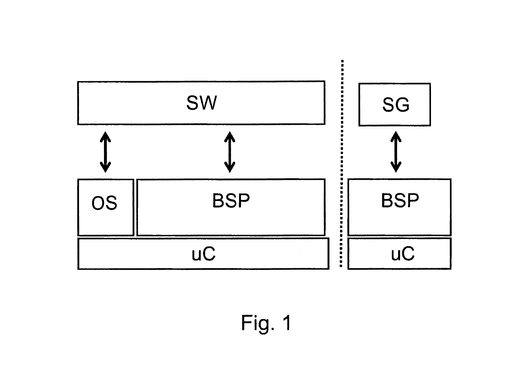
TABLE 1AbbreviationsBSP: Board support packagesECC: Error correction codeinet: Internet sourceMMU: Memory management unitMSR: Machine status registerPDF: Portable document formatPID: Process identifierQM: Quality ManagementRAM: Random Access MemoryRTOS: Real-time operating systemSG: Safety goal(s)SRS: Sharepoint sit...


PUM


Abstract

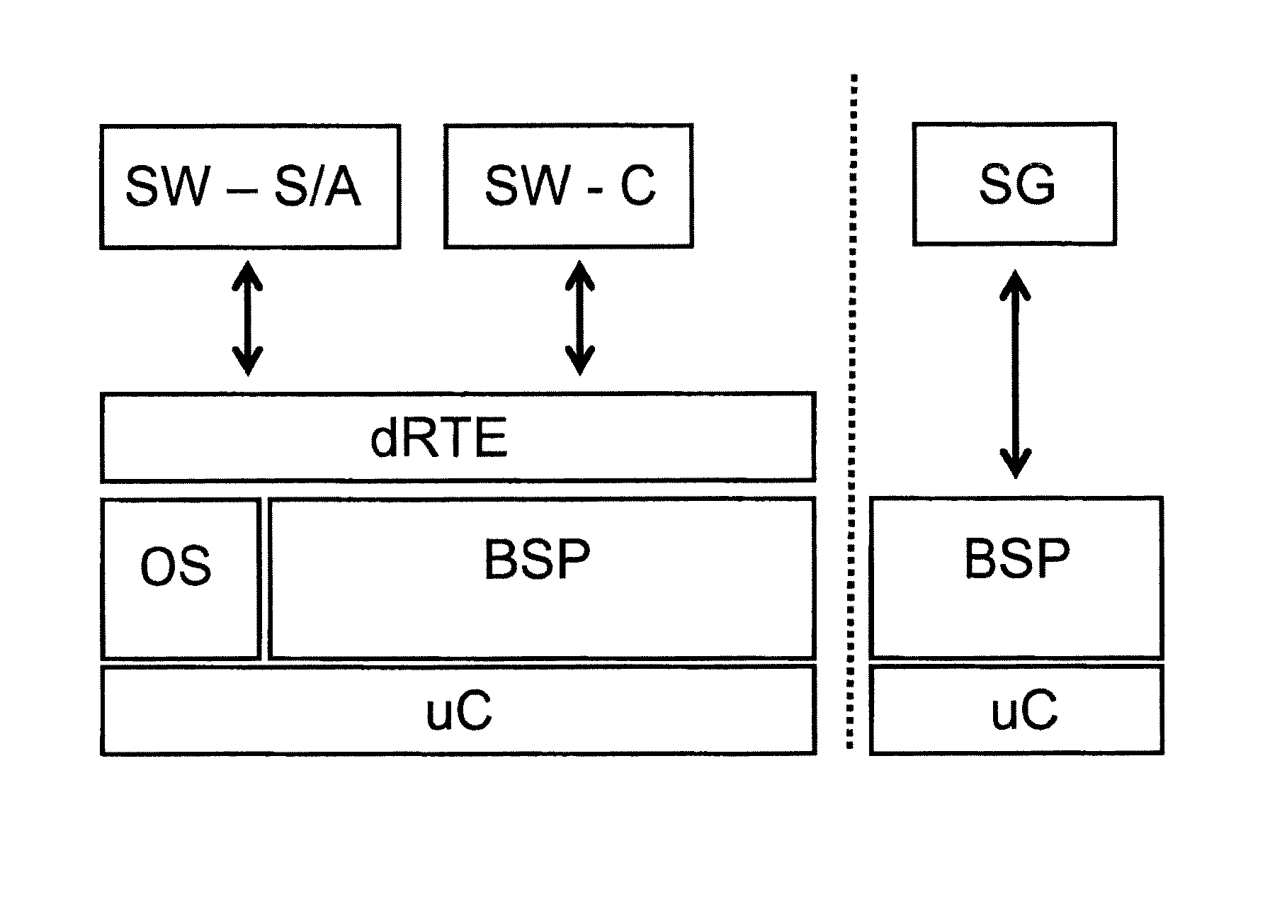
A process for decomposing safety software involves the steps of providing a first software module associated with a first logical unit, providing a second software module associated with a second logical unit, instructing the first software module to implement a first safety goal based on a quality management level, and instructing the second software module to implement a second safety goal based on a safety integrity level, where the second software module uses at least one input and at least one output of the second logical unit to determine if the second safety goal is satisfied. Consequently, the second software module uses a result of the first software module to determine if the first safety goal has been completed, and the second software module uses at least one algorithm to verify an operational status of the first logical unit.

Description

RELATED APPLICATION[0001]This application claims the benefit under 35 U.S.C. §119(e) of U.S. Provisional Patent Application Ser. No. 61 / 621,656, filed Apr. 9, 2012 and U.S. Provisional Patent Application Ser. No. 61 / 663,282, filed Jun. 22, 2012, which are incorporated by reference herein in their entirety.FIELD OF THE INVENTION[0002]The present invention relates to a functional architecture pattern used in a process to decompose software. More particularly, the present invention relates to a functional architecture pattern used in a process to decompose safety software.BACKGROUND OF THE INVENTION[0003]Currently, governments and industries are imposing functional safety standards on a variety of entities, for example, the automotive industry. Usually, these functional safety standards are realized by way of safety software that utilizes standard functional architecture patterns. Unfortunately, these functional safety standards, software, and architecture patterns are very rigid and d...

Claims


Application Information

Patent Timeline
Patent Type & Authority Patents(United States)
IPC IPC(8): G06F9/44G06F21/62G06F21/74G06F9/54
CPCG06F21/6236G06F8/10G06F8/70G06F9/54G06F21/74
Inventor THOMAS, CHRISTOPHEDUMOULIN, STEVENAELVOET, BJORN
Owner DANA BELGIUM
Learn More