
Lenses for cosine cubed, typical batwing, flat batwing distributions

a technology of cosine cubes and lenses, applied in the field of led lighting, can solve the problems of poor lighting design, drivers and pedestrians at risk in parking lots, eye-catching and a number of safety and security hazards, etc., and achieve the effect of uniform illumination and costly replacement of fluorescent lights

Active Publication Date: 2016-01-12
GE LIGHTING SOLUTIONS LLC
View PDF25 Cites 0 Cited by
  • Summary
  • Abstract
  • Description
  • Claims
  • Application Information

AI Technical Summary

Benefits of technology

The patent text explains that traditional light sources like fluorescent lamps have several problems such as high replacement costs and environmental concerns due to the use of mercury. To address these issues, LED lamps have been developed which are more efficient and environmentally friendly. The technical effects of this innovation are improved affordability, reduced maintenance costs and a more eco-friendly disposal process.

Problems solved by technology

A poor lighting design can create blinding spots of glare that cast shadows, creating an eyesore and a number of safety and security hazards.
Neglecting this element not only places drivers and pedestrians at risk in the parking lot, it can create for the business owner liability in the form of possible government fines and legal liability should an unfortunate incident occur on the premises due to poor visibility.
However, this requirement may be difficult to attain when the target area has widely varying distances.
Rather, some conventional techniques approach uniform illuminance without actually achieving “ideal” uniform illuminance.
Some LED lamps that radiate the batwing intensity distribution can produce uniform illuminance, but none can produce an intensity distribution that follows the inverted cosine cube law.

Method used


Image

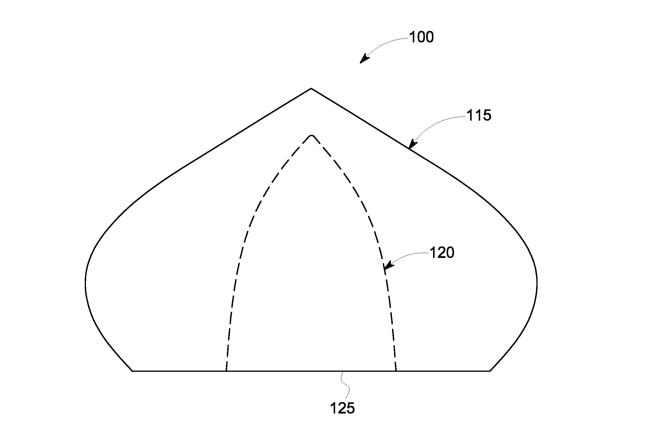
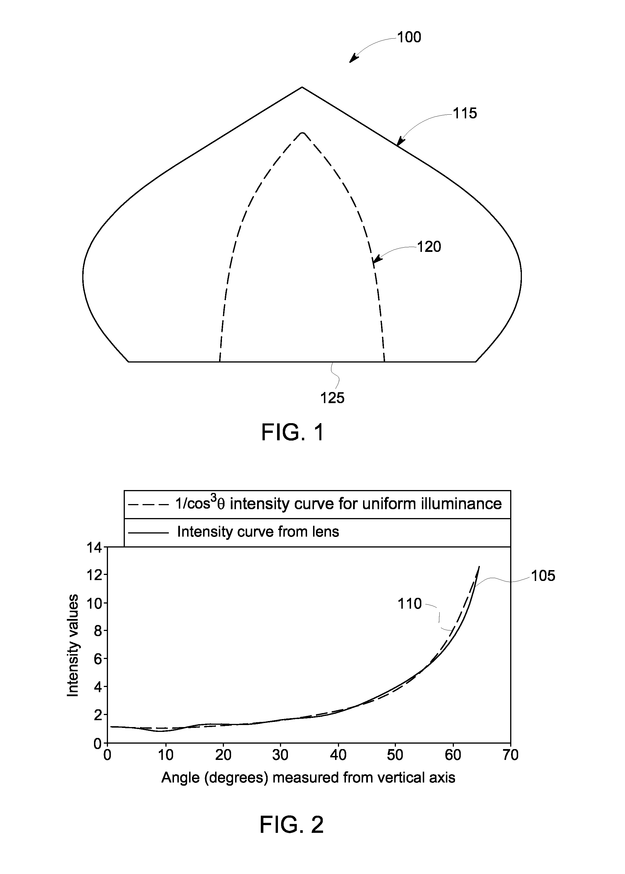
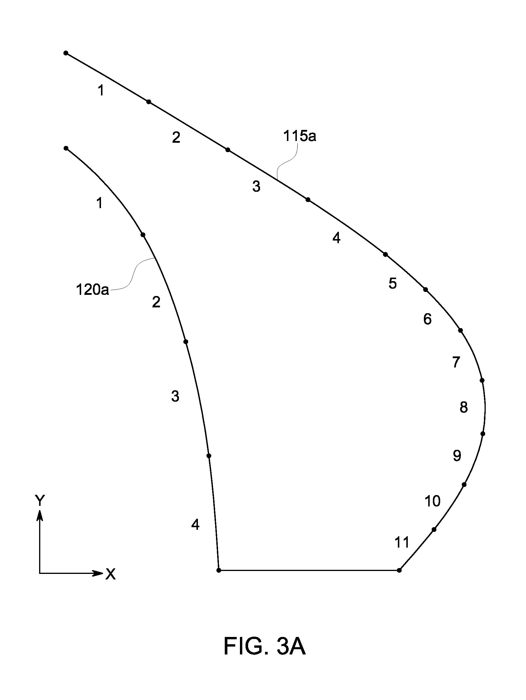
  • Lenses for cosine cubed, typical batwing, flat batwing distributions
  • Lenses for cosine cubed, typical batwing, flat batwing distributions
  • Lenses for cosine cubed, typical batwing, flat batwing distributions

Examples


Embodiment Construction

[0009]Given the aforementioned deficiencies, a need remains for a lens that gives a uniform illuminance intensity profile substantially similar to the inverted cosine cube distribution.

[0010]Furthermore, when components of traditional light sources, such as fluorescent lamps, break down and require replacement, repair of the fluorescent light can be costly in terms of both parts and labor. Also, disposal of fluorescent lamps raises environmental issues, because they contain mercury. To address the problems associated with fluorescent lamps, LED lamps provide a more efficient and environmental friendly light source than fluorescent lamps.

[0011]Therefore, there remains a need for improved lighting systems that can produce uniform illuminance on a flat surface in both retrofit and new applications. There remains a need for lenses designed for illumination by LEDs having a design that will produce uniform illumination on flat surfaces. However, some lighting applications may not require...


PUM

PropertyMeasurementUnit
angleaaaaaaaaaa
angleaaaaaaaaaa
anglesaaaaaaaaaa

Abstract

A lighting apparatus with uniform illumination distribution, according to various embodiments, can include a lens for area lighting. In one embodiment, the lens comprises a plurality of cross-sections identified by a thickness ratio defined at different angles. The thickness ratio is determined relative to the thickness of the cross-section defined at a center angle of the lens. In another embodiment, the lighting apparatus with uniform illumination distribution includes a lens having an inner surface and an outer surface. A profile of the inner surface and the outer surface is composed of a plurality of piecewise circular arcs defined with radii and circle centers. The lens is formed as a complex curve lens by joining the piecewise circular arcs of the inner surface and the outer surface.

Description

I. FIELD OF THE INVENTION[0001]The present disclosure relates generally to light emitting diode (LED) lighting. More particularly, the present disclosure relates to an LED lens producing uniform illuminance on a flat surface.II. BACKGROUND OF THE INVENTION[0002]In recent years, as their power and efficiency have increased and their cost decreased, LEDs have been used in many applications as viable replacements to conventional fluorescent lamps, incandescent lamps, neon tubes and fiber optic light sources. LED lighting systems can be employed in a variety of environments to illuminate a flat surface, such as street lighting, a parking lot, a parking garage, a roadway, a walkway, a sidewalk, an aisle, a hallway, a table, a stage, a room, a manufacturing facility, a warehouse, and other types of environments.[0003]In applying these lights to these environments, a multitude of factors influences the choice of equipment, placement of fixtures, and degrees of illumination appropriate to t...

Claims


Application Information

Patent Timeline
Patent Type & Authority Patents(United States)
IPC IPC(8): F21V5/04G02B19/00B29D11/00
CPCB29D11/00019F21V5/04G02B19/0014G02B19/0061F21Y2101/02F21Y2115/10
Inventor CHINNIAH, JEYACHANDRABOSEALLEN, GARYYODER, BENJAMIN
Owner GE LIGHTING SOLUTIONS LLC
Learn More