
Systems and Methods of Thermal Energy Storage

a technology of thermal energy storage and systems, applied in the field of thermal energy storage, can solve the problems of high storage cost, large damage to the surface of large damage to the internal heat transfer surface, so as to reduce the cost of costly repairs

Active Publication Date: 2020-05-28
ELEMENT 16 TECH INC
View PDF0 Cites 1 Cited by
  • Summary
  • Abstract
  • Description
  • Claims
  • Application Information

AI Technical Summary

Benefits of technology

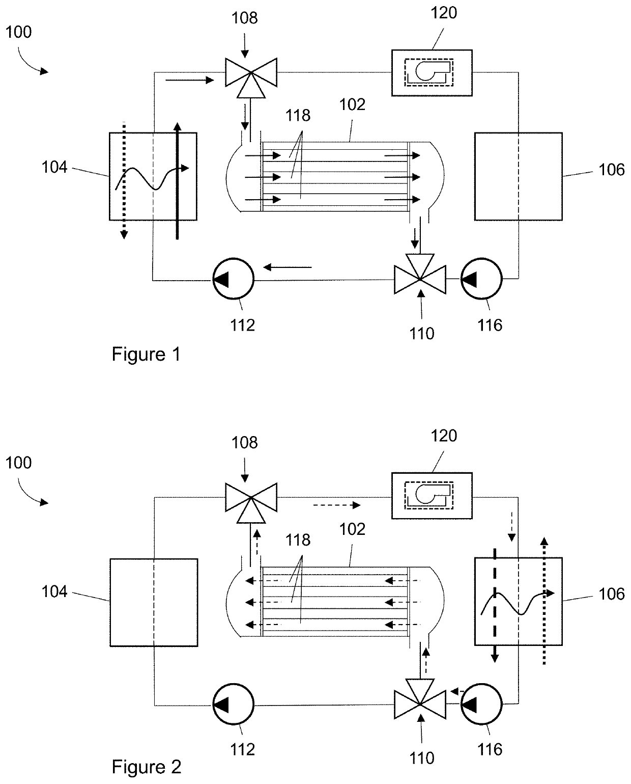
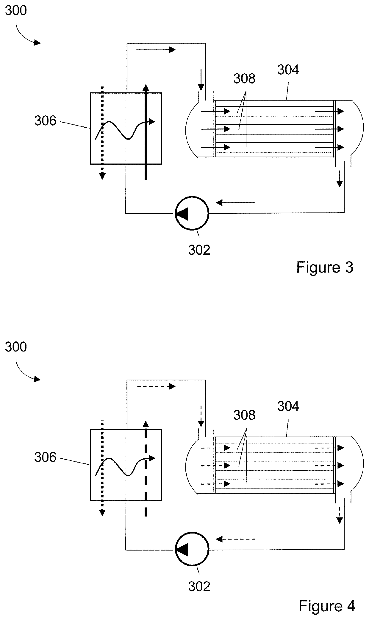
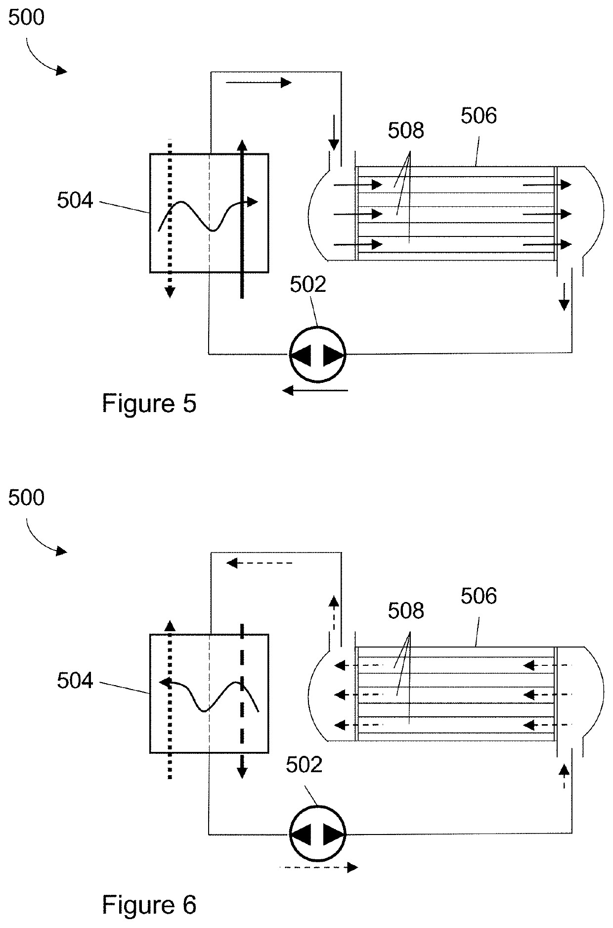
The patent is about a system that uses a heat transfer fluid to transfer heat from a working fluid to a thermal energy storage medium. The heat transfer fluid is a non-corrosive fluid that prevents damage to the system. This system helps to minimize repairs and costs by seizing corrosive fluids from the hard-to-repair internal components of the heat storage tank.

Problems solved by technology

If a dirty fluid is used directly in, for example, a sulfur heat storage system, it would cause internal heat transfer surfaces to be fouled, scaled, or corroded.
But because such systems undergo thermal cycling, having different expansion coefficients between, e.g., metals and corrosion resistant coatings on those metals can dramatically reduce the durability of the coatings.
Solutions that involve encapsulating a thermal storage medium within pipes or capsules lead to a high storage cost, and thermal storage media in the literature are typically molten salt phase change materials or solid-state storage media that exhibit slow discharge rate due to a conduction-dominated process.
Systems configured this way necessitate encapsulating a storage media in small geometries to enhance surface area per unit volume, which increases the cost and the pumping power requirement to move a heat transfer fluid through the storage system.
Dirty fluid can still be used, but others in this space have failed to consider systems that improve system reparability and longevity by keeping dirty working fluids out of the most complicated components of thermal energy storage systems.

Method used


Image

  • Systems and Methods of Thermal Energy Storage
  • Systems and Methods of Thermal Energy Storage
  • Systems and Methods of Thermal Energy Storage

Examples


Embodiment Construction

[0028]The following discussion provides example embodiments of the inventive subject matter. Although each embodiment represents a single combination of inventive elements, the inventive subject matter is considered to include all possible combinations of the disclosed elements. Thus, if one embodiment comprises elements A, B, and C, and a second embodiment comprises elements B and D, then the inventive subject matter is also considered to include other remaining combinations of A, B, C, or D, even if not explicitly disclosed.

[0029]As used in the description in this application and throughout the claims that follow, the meaning of “a,”“an,” and “the” includes plural reference unless the context clearly dictates otherwise. Also, as used in the description in this application, the meaning of “in” includes “in” and “on” unless the context clearly dictates otherwise.

[0030]Also, as used in this application, and unless the context dictates otherwise, the term “coupled to” is intended to i...


PUM


Abstract

Thermal energy storage systems are disclosed in this application. Systems of the inventive subject matter are designed to reduce maintenance requirements by sequestering, for example, corrosive fluids that might otherwise damage difficult-to-fix internal components are kept out of those components by introducing a non-corrosive heat transfer fluid to facilitate heat transfer between a thermal energy storage medium (e.g., molten sulfur) and a potentially corrosive working fluid. Thus, the potentially corrosive fluid is kept out of a thermal energy storage tank containing the thermal energy storage medium, which, by design, is difficult to repair when internal components corrode or otherwise require maintenance.

Description

FIELD OF THE INVENTION[0001]The field of the invention is thermal energy storage.BACKGROUND[0002]The background description includes information that may be useful in understanding the present invention. It is not an admission that any of the information provided in this application is prior art or relevant to the presently claimed invention, or that any publication specifically or implicitly referenced is prior art.[0003]Thermal energy storage allows excess thermal energy to be stored and used hours, days, or months later, at scales ranging from individual process, building, multiuser-building, district, town, or region. Many current technologies store heat by using a “dirty” working fluid to transfer heat to and from a thermal energy storage medium. One example of a dirty working fluid is hot pressurized water containing corrosive, scaling, and fouling properties. If a dirty fluid is used directly in, for example, a sulfur heat storage system, it would cause internal heat transfer...

Claims


Application Information

Patent Timeline
IPC IPC(8): F24H7/04
CPCF24H7/0433F28D2020/0004F28D20/0056F24H7/0466F24H9/20F28D2020/0047F28D20/0034F28D7/16F28D1/0417F28D2020/0078F28D1/05316F28D1/06F28F9/0202F01K3/00F22B1/028Y02E60/14
Inventor ARYAFAR, HAMARZNITHYANANDAM, KARTHIKWELLS, PARKER
Owner ELEMENT 16 TECH INC
Learn More