Method of arranging containers, such as bottles or cans, for forming groups of containers to be packaged as a group in a container filling plant, and apparatus therefor

a container and container filling technology, applied in the field of arranging containers, can solve problems such as certain structural restrictions, and achieve the effect of rapid adaptation to different products

Inactive Publication Date: 2015-12-29
KHS GMBH
View PDF32 Cites 2 Cited by
  • Summary
  • Abstract
  • Description
  • Claims
  • Application Information

AI Technical Summary

Benefits of technology

[0011]An object of the present application is to make it possible to adapt the grouping devices with the maximum possible flexibility, which renders a corresponding plant suitable for the handling of very different products with an accurate positioning of the contact elements.SUMMARY
[0013]With the present application, it is possible to provide at least three pairs of chains or similar components at the point of product group formation with corresponding contact elements and to position these contact elements so that different group sizes are made possible.
[0019]To make possible a rapid adaptation to different products, the present application also teaches that the contact elements can be pivoted into or below the plane of the cross beams when they are not being used, whereby the contact elements on the cross beams can also be interchangeable and / or variable in terms of their position or their distance from one another.

Problems solved by technology

An additional problem is that it is desirable to be able to insert the contact elements from below very exactly perpendicularly or substantially perpendicular upward between the products being transported, i.e. go avoid, restrict, and / or minimize any upward pivoting movement to prevent, restrict, and / or minimize the formation of a fulcrum, for which purpose guides, e.g. in the form of contact grooves, are provided on the side cheeks of the device frame, although the presence of these guides can also result in certain structural restrictions.

Method used


Image

  • Method of arranging containers, such as bottles or cans, for forming groups of containers to be packaged as a group in a container filling plant, and apparatus therefor
  • Method of arranging containers, such as bottles or cans, for forming groups of containers to be packaged as a group in a container filling plant, and apparatus therefor
  • Method of arranging containers, such as bottles or cans, for forming groups of containers to be packaged as a group in a container filling plant, and apparatus therefor

Examples


Embodiment Construction

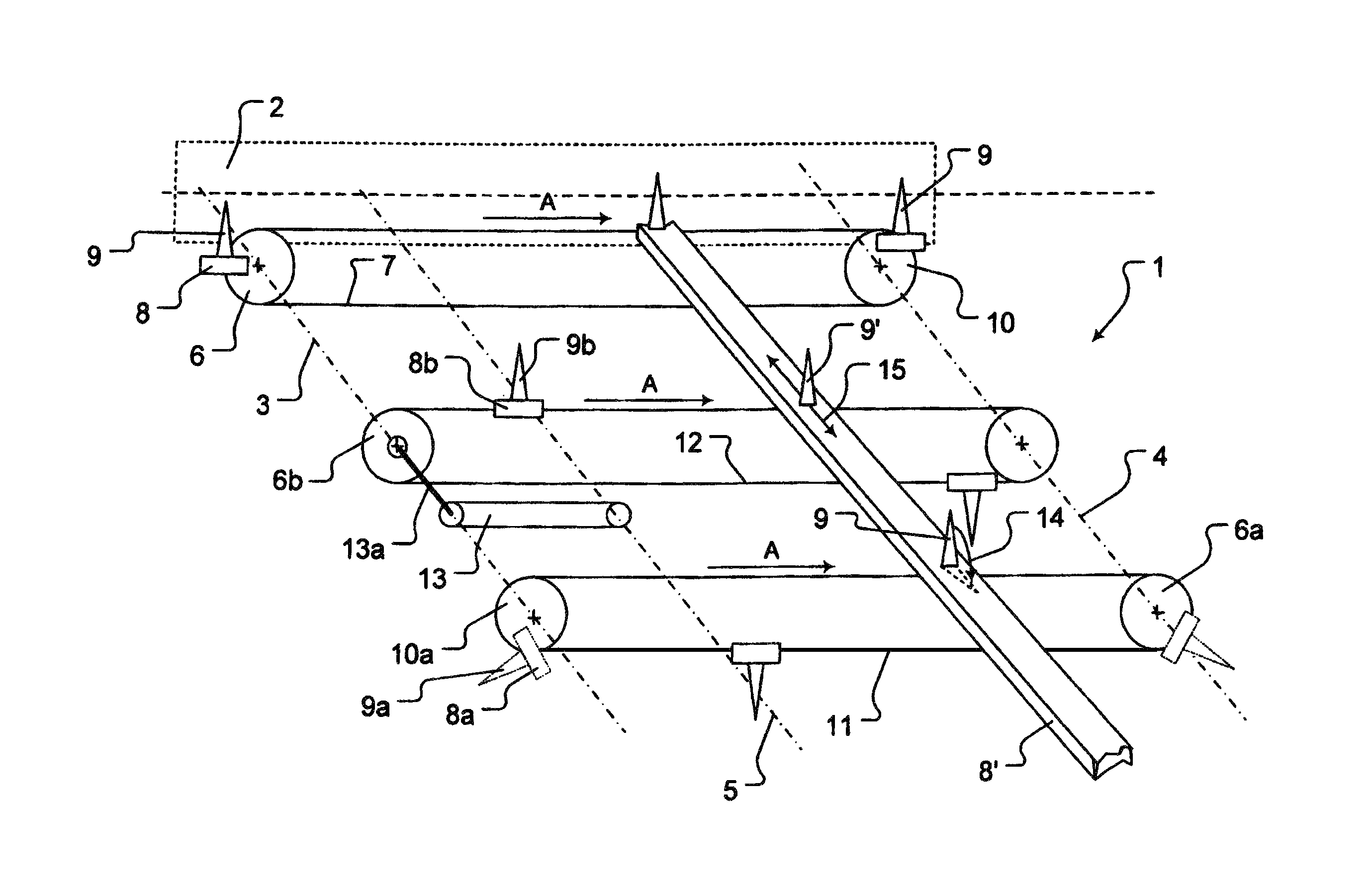
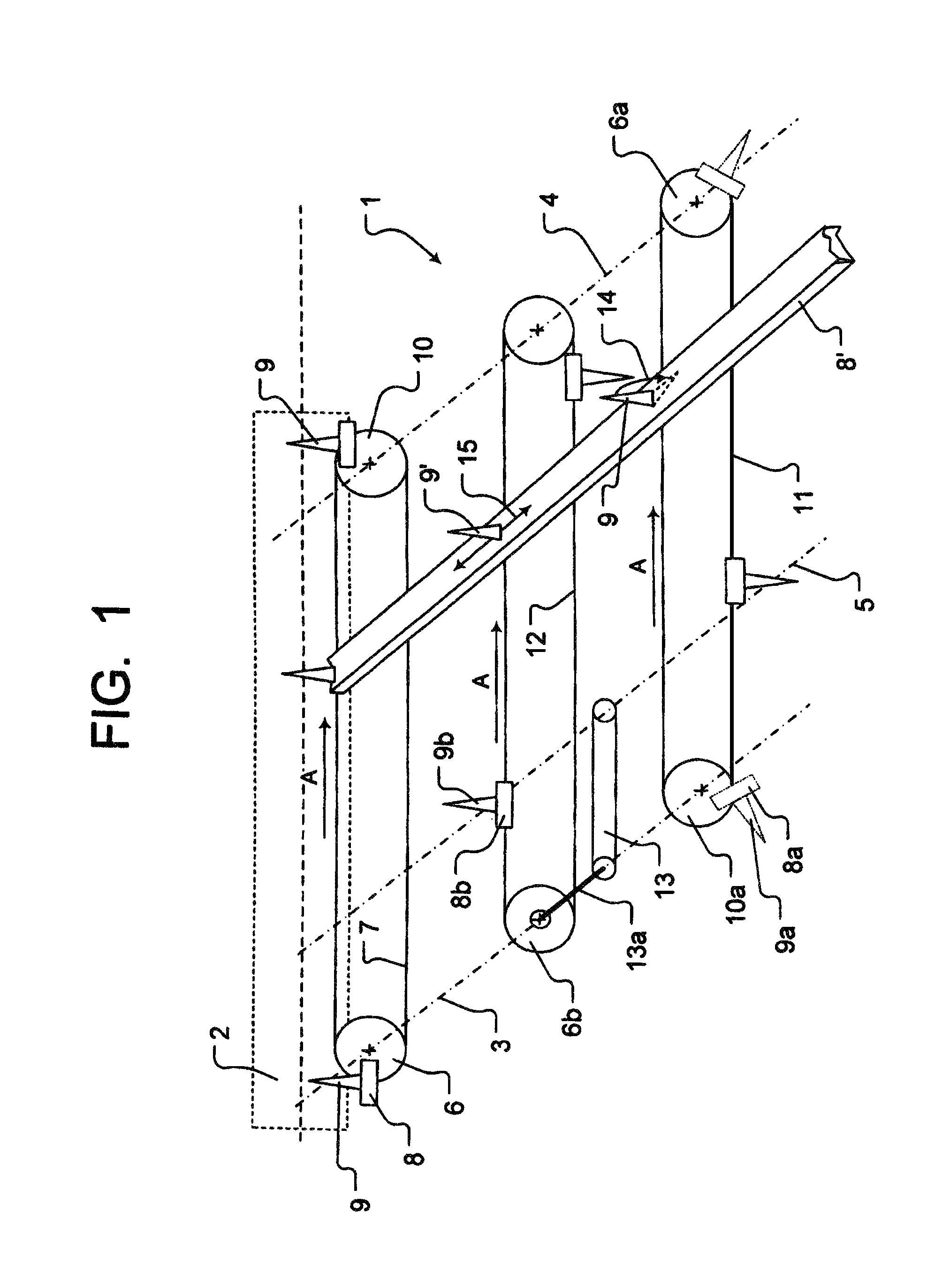
[0035]Of the device according to the present application, which is designated 1 in general, one side cheek of the device frame 2 is illustrated schematically, in which three shafts are mounted, namely an end shaft 3 on the left side of the figure in FIG. 1, an end shaft 4 positioned on the other end of the device and a shaft designated 5 positioned between them, each of which is used to drive a chain pair, whereby FIG. 1 shows one endless chain of each chain pair.

[0036]Although the motorized drives, e.g. in the form of servomotors, are not shown here, a chain drive sprocket 6 of the first chain, designated 7 here, of a chain pair is driven by means of the shaft 3, whereby this chain pair is equipped with cross beams 8 oriented across the entire width of the device 1 and equipped with the indicated contact elements 9.

[0037]The shaft 4 carries a planetary wheel designated 10 for the circulating chain. The shaft 4 is simultaneously or substantially simultaneously used, by means of a mo...


PUM

PropertyMeasurementUnit
right angleaaaaaaaaaa
lengthaaaaaaaaaa
distanceaaaaaaaaaa

Abstract

An article-grouping device which has at least three independently-driven drive arrangements and a plurality of divider elements located on crossbeams. Each of the drive arrangements moves the crossbeams, and thus moves the divider elements thereon to a position between adjacent articles in a stream of articles on a conveyor arrangement to divide the stream of articles into separated groups of articles. Each of the drive arrangements comprises a drive shaft and a pair of elongated driven elements, such as endless chains or toothed belts. At least two of the drive shafts both drive a pair of driven elements and support pairs of driven elements driven by other drive shafts.

Description

CONTINUING APPLICATION DATA[0001]This application is a Continuation-In-Part application of International Patent Application No. PCT / EP2008 / 006117, filed on Jul. 25, 2008, which claims priority from Federal Republic of Germany Patent Application No. 10 2007 038 827.8, filed on Aug. 16, 2007. International Patent Application No. PCT / EP2008 / 006117 was pending as of the filing date of this application. The United States was an elected state in International Patent Application No. PCT / EP2008 / 006117.BACKGROUND[0002]1. Technical Field[0003]The present application relates to a device for the formation of product groups from a stream of a plurality of identical or substantially identical packaged goods that are fed via conveyor devices with a delivery path and divider elements on at least one pair of driven, endless circulating chains, toothed belts etc., which divider elements are cyclically engaged in the product stream at a right angle to the plane of transport.[0004]2. Background Informa...

Claims


Application Information

Patent Timeline
Patent Type & Authority Patents(United States)
IPC IPC(8): B65G21/06B65G47/28B65G47/08B65G17/26B65G47/84
CPCB65G47/088B65G17/26B65G47/28B65G47/841B65G21/06B65G2201/0244B65B21/06
Inventor RIPKENS, HANS-GERDSCHAGIDOW, TUCHWATKAMPS, SEBASTIANRUTTEN, THOMAS
Owner KHS GMBH
Why Eureka
Try Eureka