Eureka AIR delivers breakthrough ideas for toughest innovation challenges, trusted by R&D personnel around the world.

Partition wall for an aeroplane cabin, and an aeroplane

a technology for aeroplane cabins and partition walls, applied in the direction of aircraft crew accommodation, transportation and packaging, weight reduction, etc., can solve the problems of high level of manual intervention in production, high level of automation, and easy detachment of cover layers from honeycomb cores, etc., to achieve the maximum flexibility and optimise the planar structure

Active Publication Date: 2015-11-10
AIRBUS OPERATIONS GMBH
View PDF27 Cites 7 Cited by
  • Summary
  • Abstract
  • Description
  • Claims
  • Application Information

AI Technical Summary

Benefits of technology

[0005]The object of the invention is to create a partition wall for the separation of cabin areas of an aeroplane, which removes the above-cited disadvantages and in the course of leaner production has the maximum possible flexibility with regard to accessories as well as an optimised planar structure, and to create an aeroplane whose partition walls enable a multiplicity of different configurations of accessories.

Problems solved by technology

This results in a multiplicity of variants of embodiment, as a result of which automated production is almost impossible and the level of manual intervention in production is very high.
However, in the event of fire the cover layers often have a tendency to detach from the honeycomb core.

Method used


Image

  • Partition wall for an aeroplane cabin, and an aeroplane
  • Partition wall for an aeroplane cabin, and an aeroplane
  • Partition wall for an aeroplane cabin, and an aeroplane

Examples


Embodiment Construction

[0029]In the figures the same constructive elements have the same reference numbers, wherein in the interests of clarity only some of the elements are provided with a reference number in some of the figures.

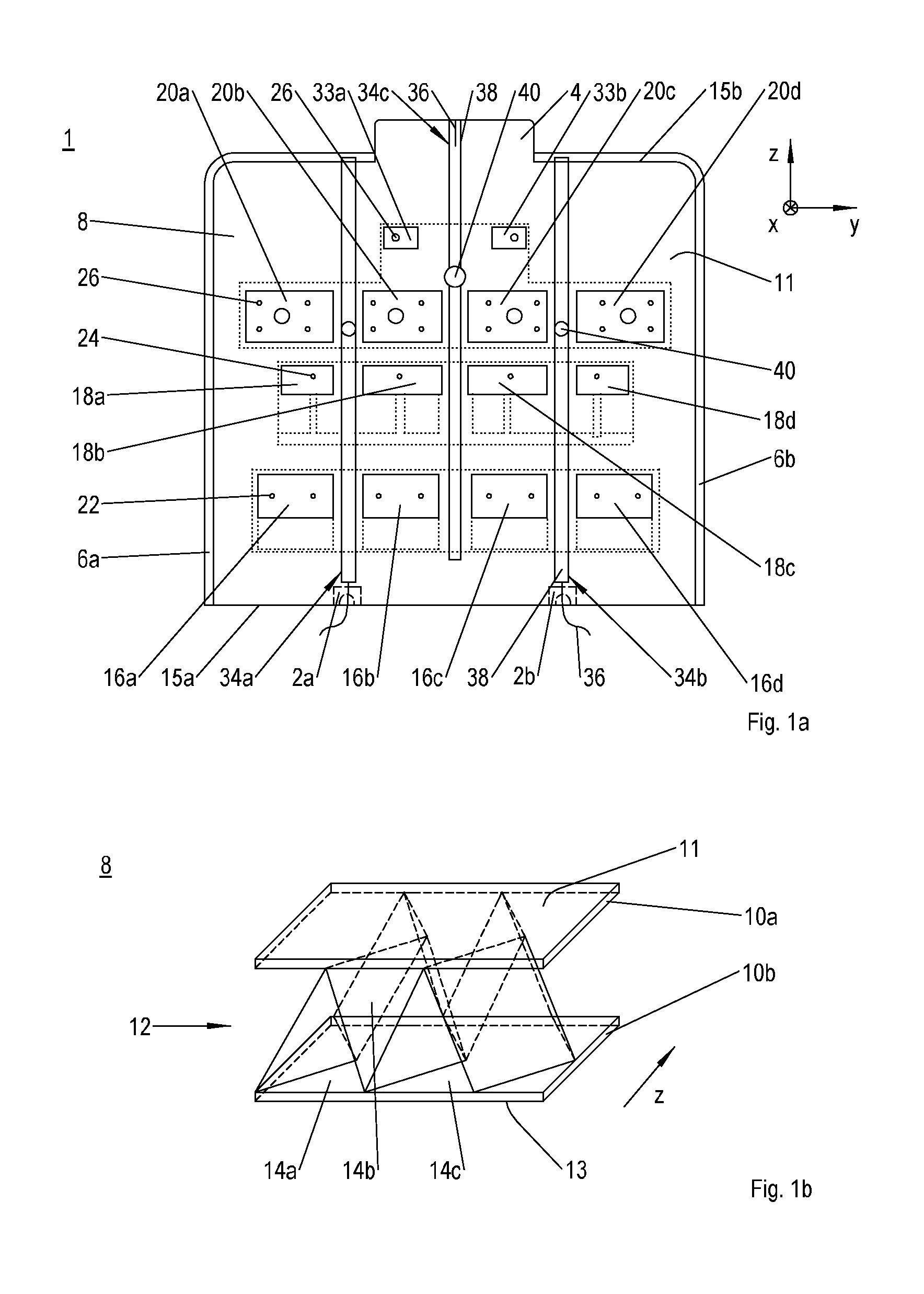
[0030]FIG. 1a shows an inventive partition wall 1 for the separation of cabin areas in an aeroplane. It extends laterally from a cabin gangway, or between two cabin gangways, in the transverse direction y of the aeroplane, and forms two cabin areas arranged one behind another in the longitudinal direction x of the aeroplane. It has, for example, two foot attachment sections 2a, 2b for purposes of attachment to seating rails in the floor, and a head projection 4 for purposes of attachment to an aeroplane structural section in the ceiling. In order to prevent damage to the partition wall 1 in the border regions visible between the attachment sections 2a, 2b and the projection 4, these border regions are encompassed in each case by edge protection 6a, 6b.

[0031]In accordance with FI...


PUM


Abstract

A standardized / modularized partition wall with a basic sandwich structure for purposes of separating a cabin area of an aeroplane. The partition wall has a multiplicity of defined zones for the flexible positioning of holding fixtures for the connection of accessories such as flat screens, baby carriers, newspaper racks, and similar, and which is dimensioned for a maximum population with accessories.

Description

CROSS-REFERENCES TO RELATED APPLICATIONS[0001]This application claims the benefit of the U.S. Provisional Application No. 61 / 426,528, filed on Dec. 23, 2010, and of the German patent application No. 10 2010 064 100.6 filed on Dec. 23, 2010, the entire disclosures of which are incorporated herein by way of reference.BACKGROUND OF THE INVENTION[0002]The invention concerns a partition wall for an aeroplane cabin and an aeroplane.[0003]Partition walls make possible the subdivision of an aeroplane cabin into areas fitted out with different levels of comfort, such as e.g. first class and economy class. Partition walls of this kind are of known art from DE 10 2008 016 419 A1 or US 20090242149 A1, amongst others. As a rule the function of the partition walls, however, is not only in the separation of cabin areas, but also in the attachment of accessories, such as e.g. flat screens, newspaper racks and baby carriers. Since the position of the partition walls within the cabin as well as their...

Claims


Application Information

Patent Timeline
Patent Type & Authority Patents(United States)
IPC IPC(8): B64D11/00
CPCB64D11/0023Y02T50/46Y02T50/40
Inventor HELFRICH, FELIXWARNER, HOLGER
Owner AIRBUS OPERATIONS GMBH
Why Eureka
Eureka Blog
Learn More