
Synchronization through waveform correlation

a waveform and synchronization technology, applied in the direction of synchronisation signal speed/phase control, synchronisation error correction, digital transmission, etc., can solve the problems of mediums being susceptible to noise, difficult to identify in digital data streams, and communication systems having limitations associated

Active Publication Date: 2015-12-22
L3 TECH INC
View PDF17 Cites 6 Cited by
  • Summary
  • Abstract
  • Description
  • Claims
  • Application Information

AI Technical Summary

Benefits of technology

The patent describes a method for detecting the timing of a synchronization sequence in a noisy communication channel. The method involves obtaining a data stream waveform, including the synchronization sequence, and comparing it to a model waveform to determine the expected waveform. This allows for accurate synchronization and data recovery in the communication system. The technical effect of this invention is improved synchronization and data recovery in communication systems, even in the presence of noise.

Problems solved by technology

Virtually every communication system has some limitations associated with it.
Additionally, the mediums may be susceptible to noise which can mask or otherwise overpower data in a digital signal.
Indeed, small noise sources from molecular vibrations to large intentional jamming noise sources can drown out digital signals to make them very difficult to identify in a digital data stream.
In many such systems, the data stream (including the synchronization sequence and other payload data) is sparse, meaning that there are long temporal gaps between bursts of data.
However, in sparse data streams, it may be difficult to use such feedback type arrangements as there is not a constant input data stream, and such systems therefore typically have poor performance in sparse data stream environments.

Method used


Image

  • Synchronization through waveform correlation
  • Synchronization through waveform correlation
  • Synchronization through waveform correlation

Examples


Embodiment Construction

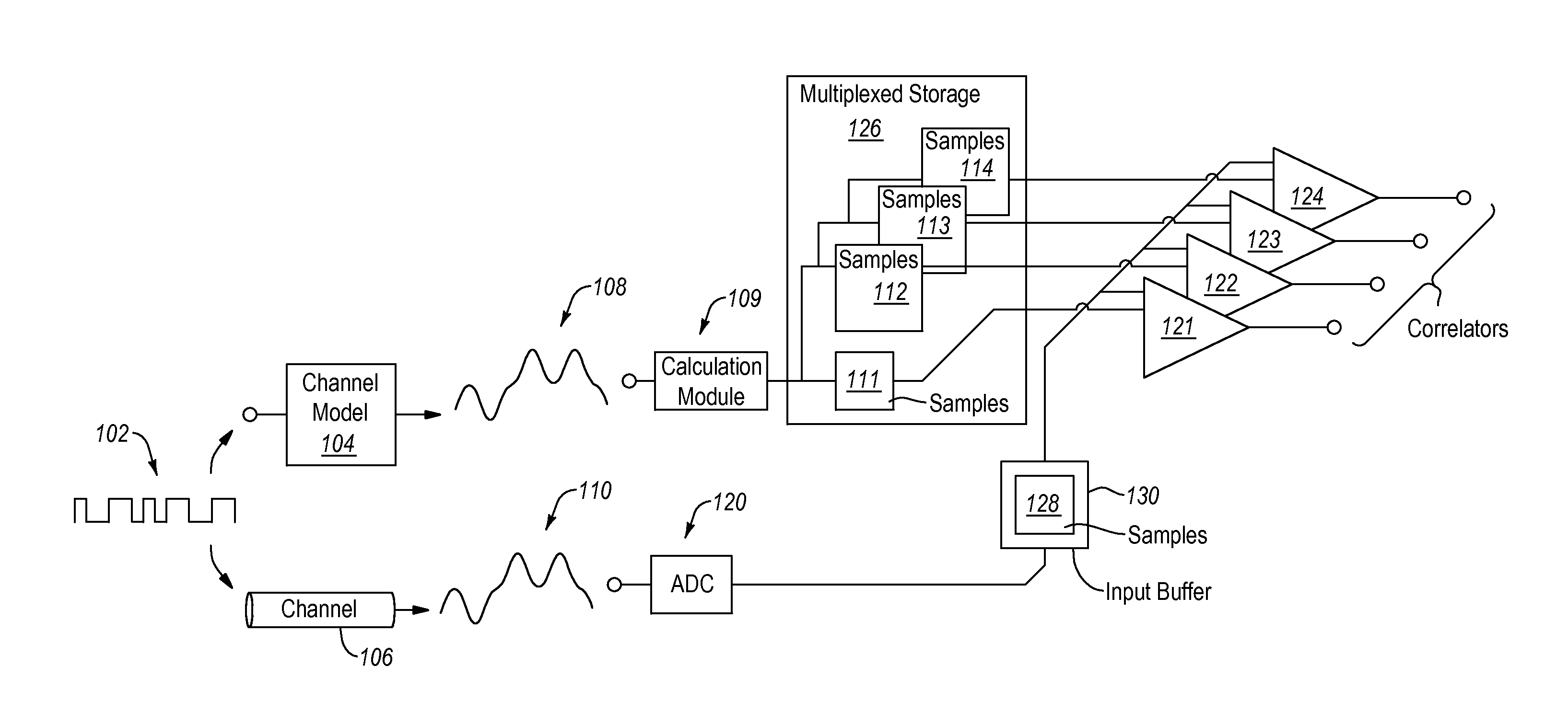
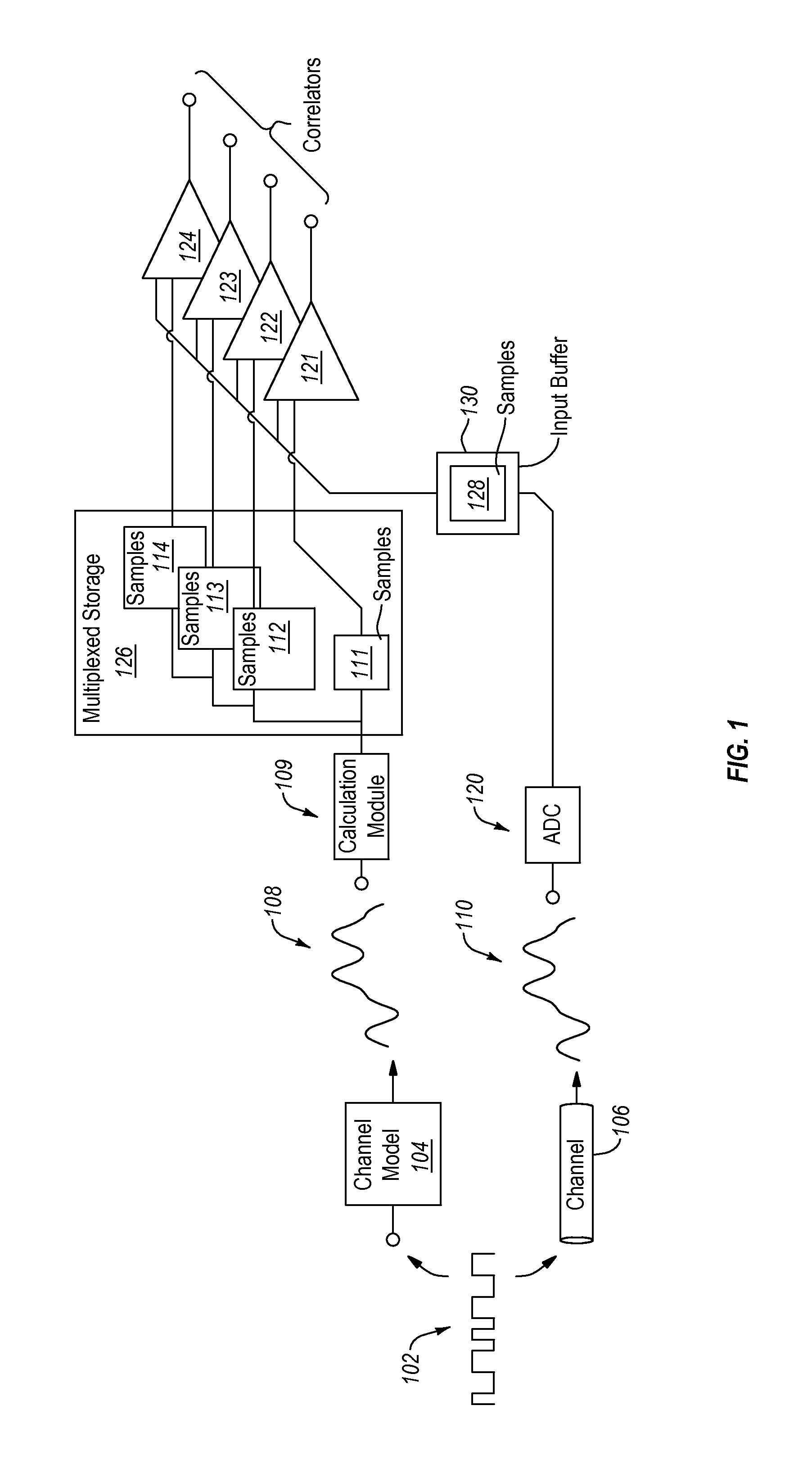
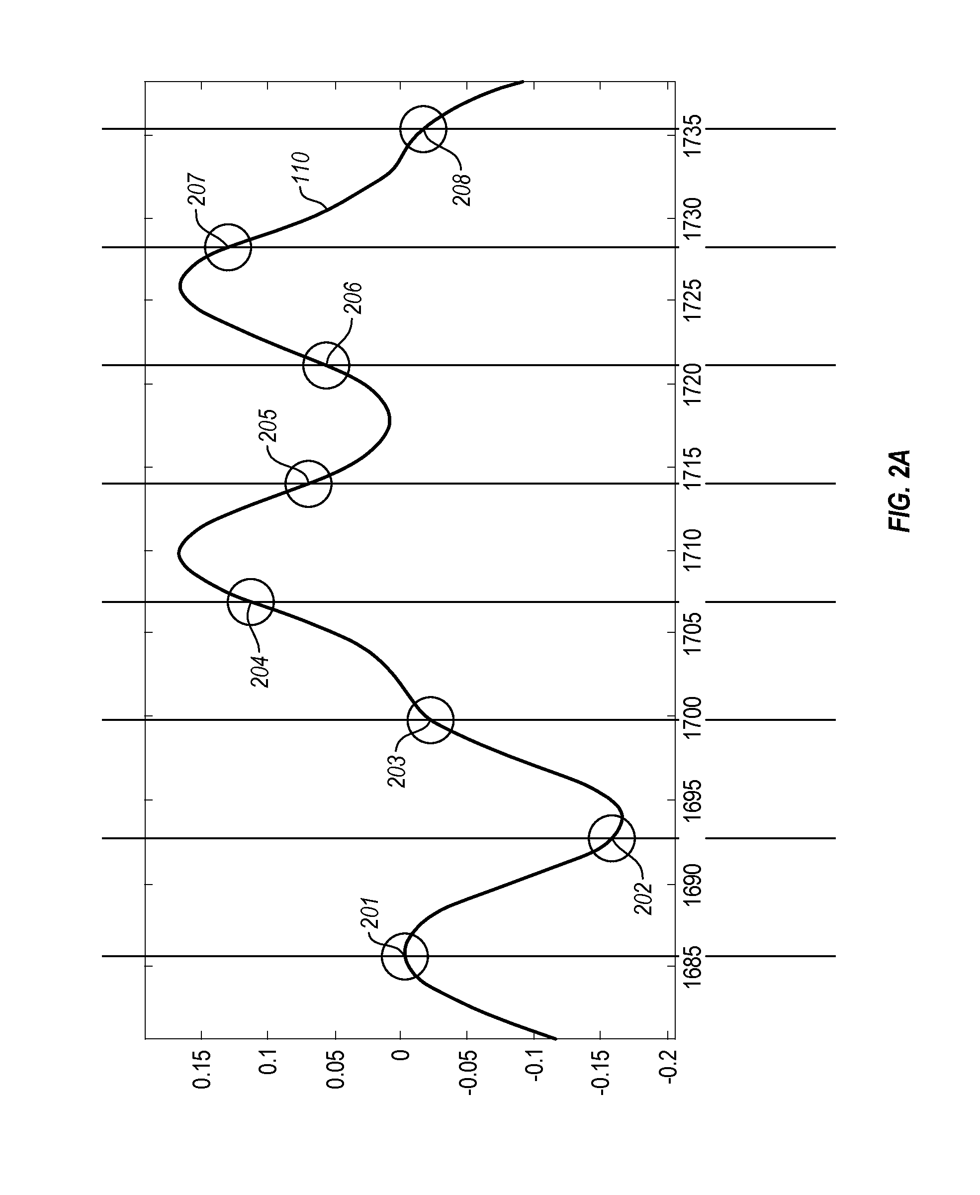
[0031]Embodiments described herein use a model-based correlator to detect a synchronization sequence, sometimes referred to as a unique word. In particular, embodiments may produce a model synchronization sequence waveform by passing the synchronization sequence through a noise free model of a communication channel, including modeling of various filters in the channel. The synchronization sequence is also received by the actual communication channel, which has significant noise, producing a synchronization sequence waveform. Sample points can be taken for several different alignments of the model synchronization sequence waveform. Sample points can also be taken for the synchronization sequence waveform. Note that the sample rate and the data rate of the synchronization sequence waveform may be non-commensurate resulting in some sample points that convey significant amounts of information (e.g. when a sample is taken near a peak) about the synchronization sequence waveform and some ...


PUM


Abstract

Detecting timing of a synchronization sequence included in a data stream transmitted in a noisy channel. The synchronization sequence is a known data sequence purposely injected into the data stream for synchronization. A data stream waveform, is obtained from a noisy communication channel. The data stream waveform includes an instance of a synchronization sequence waveform. One or more samples of the synchronization sequence waveform are obtained. One or more samples of a model synchronization sequence waveform are obtained. The model synchronization sequence waveform models an expected waveform for the synchronization sequence being transmitted on the communication channel by applying the synchronization sequence to a model of the communication channel. The instance of the synchronization sequence waveform is correlated with the model synchronization sequence waveform by correlating one or more samples of the synchronization sequence waveform with the one or more samples of the model synchronization sequence waveform.

Description

BACKGROUNDBackground and Relevant Art[0001]Digital data communications are ubiquitous in today's modern society. Such communication can take one or more of a number of different forms. For example, communications may take place at the micro-level when binary bits are transmitted across microscopic circuits within an integrated circuit. At the other extreme, communication may travel long distances by use of satellite or other long distance transmission systems. Indeed communications are regularly undertaken with machines and individuals around the world and beyond.[0002]To accomplish such communications requires the use of one or more transmission systems and associated mediums. Such mediums may be, for example, integrated circuit paths, wires, optical fibers, or even over the air. Virtually every communication system has some limitations associated with it. In particular, any given communication medium may attenuate digital signals transmitted across it. Additionally, the mediums ma...

Claims


Application Information

Patent Timeline
IPC IPC(8): H04L7/033H04L7/00
CPCH04L7/0331H04L7/0016H04L7/0029H04L7/042H04L7/10
Inventor LANDON, DAVID G.NELSON, DAVID S.DICKSON, ROBERT L.YOHO, BRIAN G.CHRISTENSEN, CARL
Owner L3 TECH INC
Learn More