
Discretely supported wet side plates

a wet side plate and discrete support technology, applied in the direction of cell components, final product manufacturing, sustainable manufacturing/processing, etc., can solve the problems of fuel cell thickness and part count, and achieve the effect of increasing dry side flow channel thickness, fuel cell thickness and part count, and efficient water vapor transfer

Active Publication Date: 2015-12-01
GM GLOBAL TECH OPERATIONS LLC
View PDF4 Cites 7 Cited by
  • Summary
  • Abstract
  • Description
  • Claims
  • Application Information

AI Technical Summary

Benefits of technology

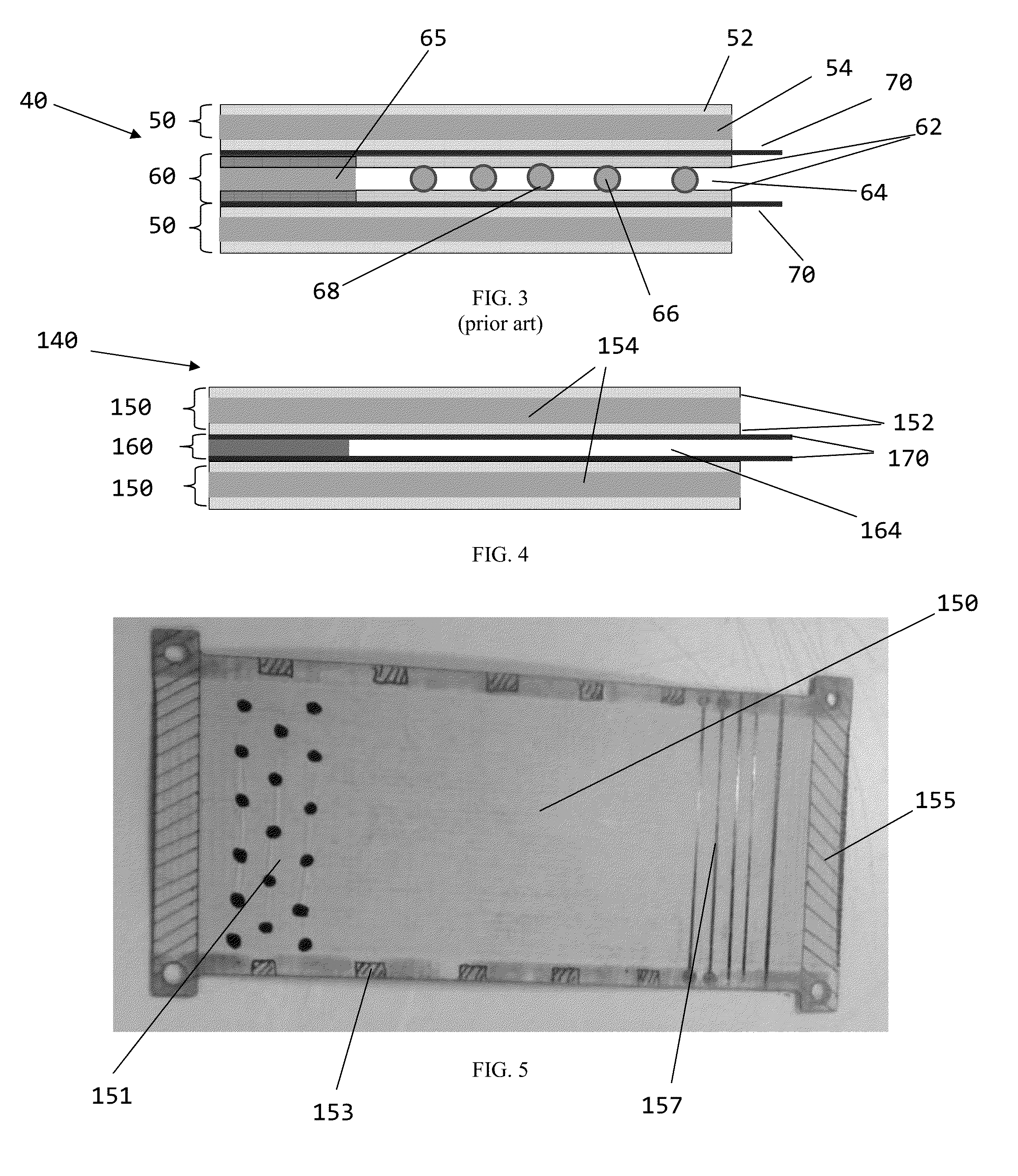
The present invention provides a separator plate assembly for a water vapor transfer device that is thinner, lighter, and simpler to fabricate than conventional assemblies. The assembly includes a pair of wet side separators with WVT membranes placed on their surfaces, and edge strips positioned on the membranes. The wet side WVT membranes define a dry side flow channel between them. The assembly can be made without the traditional dry-side separator plate, which can be replaced with spacers and discrete supports. The spacers and supports ensure uniform spacing between plates and evenly distributed dry side mass flow throughout the WVT stack. The WVT assembly with the discretely supported wet side plates has improved water transfer rate performance, lower costs, and reduced mass and part count.

Problems solved by technology

Moreover, the presence of the wet side WVT membranes defining the opposing top and bottom (or side to side, depending on the fuel cell orientation) surfaces of the dry side flow channel mean that redundant membrane structure is absent or eliminated, which further contributes to fuel cell thickness and part count.

Method used


Image

  • Discretely supported wet side plates
  • Discretely supported wet side plates
  • Discretely supported wet side plates

Examples


Embodiment Construction

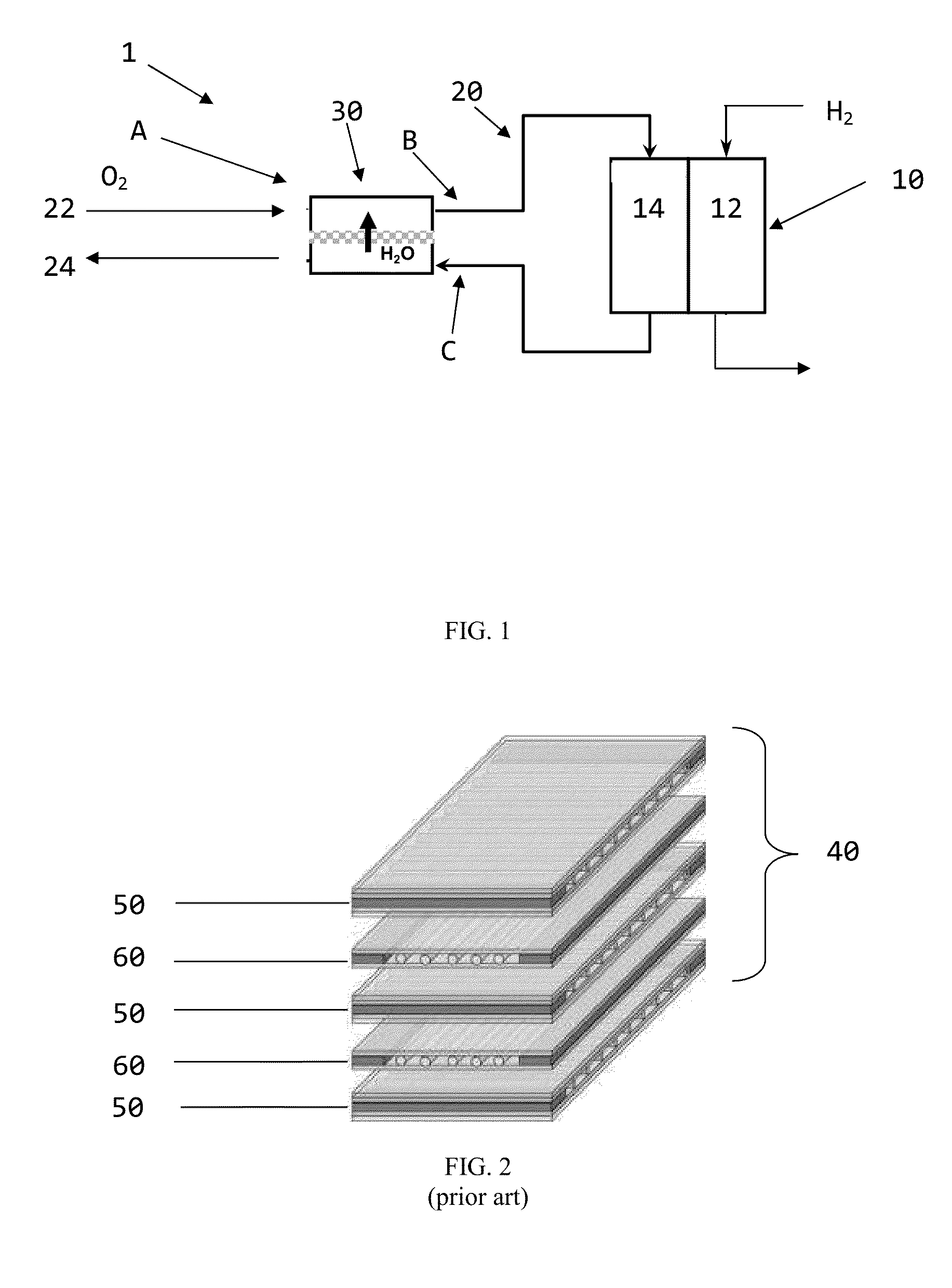
[0023]Referring first to FIG. 1, a fuel cell system 1 made up of a fuel cell stack 10 with numerous individual fuel cells, each of which has an anode 12 and cathode 14, is shown. Various flowpaths are used to convey reactants and their byproducts to and from the respective anode 12 and cathode 14. A WVT unit 30 is fluidly coupled to appropriate portions of flowpath 20 to promote the exchange of humidity between the exhaust 24 and the feed 22. As shown with particularity for the cathode 14, dry air from a compressor (not shown) is fed through feed 22 over a range of pressures and low humidity (typically around 0%) into the WVT unit 30. Likewise, exhaust being discharged from cathode 14 passes through exhaust 24 to the WVT unit 30. The cathode exhaust 24 is at a lower pressure and higher humidity than the air entering the WVT unit 30 on the feed 22 side. Inside the WVT unit 30 is a core made up of numerous wet side and dry side plates which are stacked in an alternating arrangement su...


PUM

PropertyMeasurementUnit
heightaaaaaaaaaa
heightaaaaaaaaaa
heightaaaaaaaaaa

Abstract

A water vapor transfer separator plate assembly and a method of making the same. In such an assembly made up of a stack of alternating wet side plates and dry side plates with a membrane disposed between them, a humid fluid such as that found in a fuel cell cathode exhaust flows against one side of each membrane such that at least some of its moisture content travels across the membrane to a lower humidity fluid on the opposite side of the membrane. The lower humidity fluid, such as that found in a fuel cell cathode entrance, experiences an increase in its humidity by the operation of the moisture flow across the membrane. At least a portion of the assembly may be made thinner by removing diffusion media and reinforcing structure of the dry side plates such that the overall assembly is simplified.

Description

[0001]This application claims the benefit of the filing dates of U.S. Provisional Application No. 61 / 434,569, filed Jan. 20, 2011.BACKGROUND OF THE INVENTION[0002]This invention relates generally to a way to improve the transfer of water vapor produced by a fuel cell, and more particularly to an improved water vapor transfer (WVT) separator plate assembly and a method for making such an assembly.[0003]In many fuel cell systems, hydrogen or a hydrogen-rich gas is supplied through a flowfield to the anode side of a fuel cell while oxygen (such as in the form of atmospheric oxygen) is supplied through a separate flowfield to the cathode side of the fuel cell. An appropriate catalyst (for example, platinum) is typically disposed as a layer on porous diffusion media that is typically made from a carbon fabric or paper such that it exhibits resiliency, electrical conductivity, and gas permeability. The catalyzed diffusion media is used to facilitate hydrogen oxidation at the anode side an...

Claims


Application Information

Patent Timeline
Patent Type & Authority Patents(United States)
IPC IPC(8): H01M8/24B01F3/04H01M8/02H01M8/04H01M8/10
CPCH01M8/0267H01M8/0228H01M8/04291Y10T156/1089Y02E60/50Y10T156/1026H01M2008/1095H01M8/0258Y02P70/50H01M8/0297
Inventor MARTINCHEK, DAVID A.BRONCHETTI, THOMAS D.
Owner GM GLOBAL TECH OPERATIONS LLC
Learn More