
Accelerated compute tessellation by compact topological data structure

a topological data structure and compute tessellation technology, applied in computing, 3d-image rendering, instruments, etc., can solve the problems of limiting modern system resources, wasting processing resources, and rendering such a complex design can exhaust processing resources, etc., and achieves the effect of reducing the cost of rendering and other applications, such as real-time rendering (e.g., video)

Active Publication Date: 2015-11-24
ADVANCED MICRO DEVICES INC
View PDF1 Cites 2 Cited by
  • Summary
  • Abstract
  • Description
  • Claims
  • Application Information

AI Technical Summary

Benefits of technology

The invention describes a method for identifying the inner ring, outer edge, and stitch of a patch, and then using those data points to create tessellated credits for the patch. This process can be performed by a computing device, either alone or with the help of other shaders. The technical effect is a more accurate and precise way of generating detailed information about a patch of material, which can be useful in various industries such as manufacturing and design.

Problems solved by technology

These applications tax modern system resources to the limit, requiring significant memory space to buffer vertex information defining three-dimensional (3D) models and their texture data, as well as graphics processing unit (GPU) clock cycles for their manipulation.
For example, while a 3D artist can readily make a very realistic model using many vertices, actually rendering such a complex design can exhaust processing resources.
However, this tradeoff is unacceptable in other applications, such as real-time rendering (e.g., video games).
Having a large number of vertices makes real-time manipulation of a model very challenging.
Vertex shaders, which perform operations on a per-vertex basis (e.g., application of a transform matrix), quickly become a computational bottleneck with too many vertices to operate on.
While this concept allows software developers to create simpler, less computationally-intensive models that nevertheless result in realistic visualizations, several challenges remain.
Moreover, the tessellation techniques applied by the fixed tessellation stage are highly serial in operation, requiring multiple processor clock cycles for the tessellation of each input patch (typically one clock cycle per new object created).

Method used


Image

  • Accelerated compute tessellation by compact topological data structure
  • Accelerated compute tessellation by compact topological data structure
  • Accelerated compute tessellation by compact topological data structure

Examples


Embodiment Construction

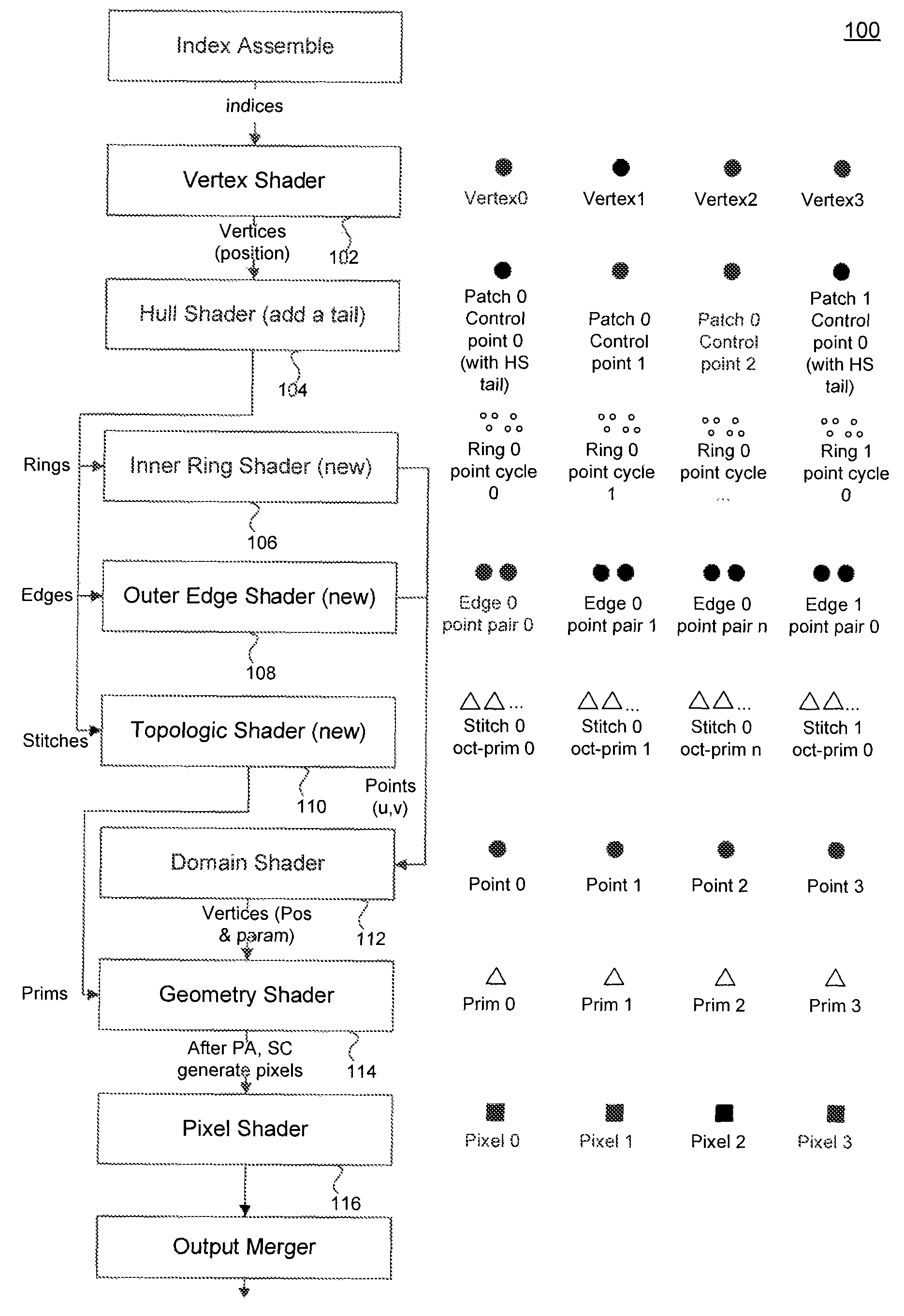
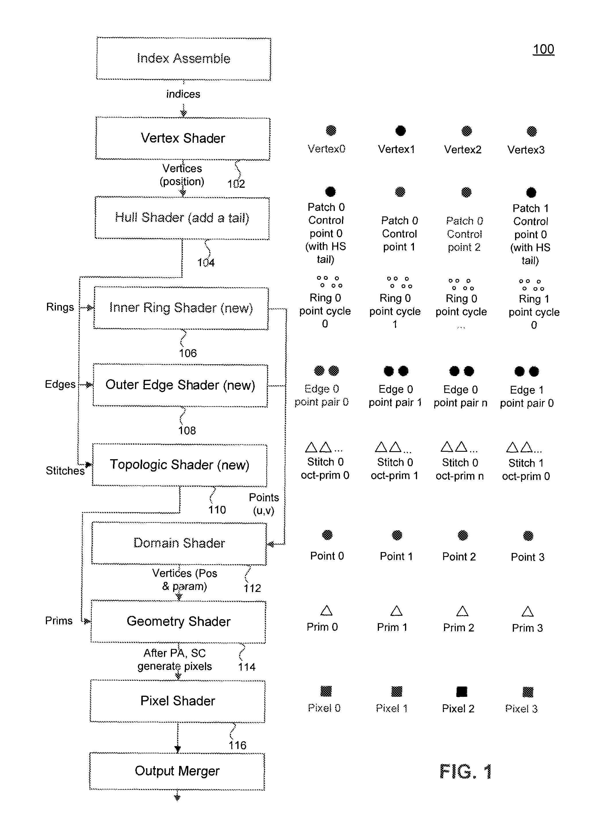
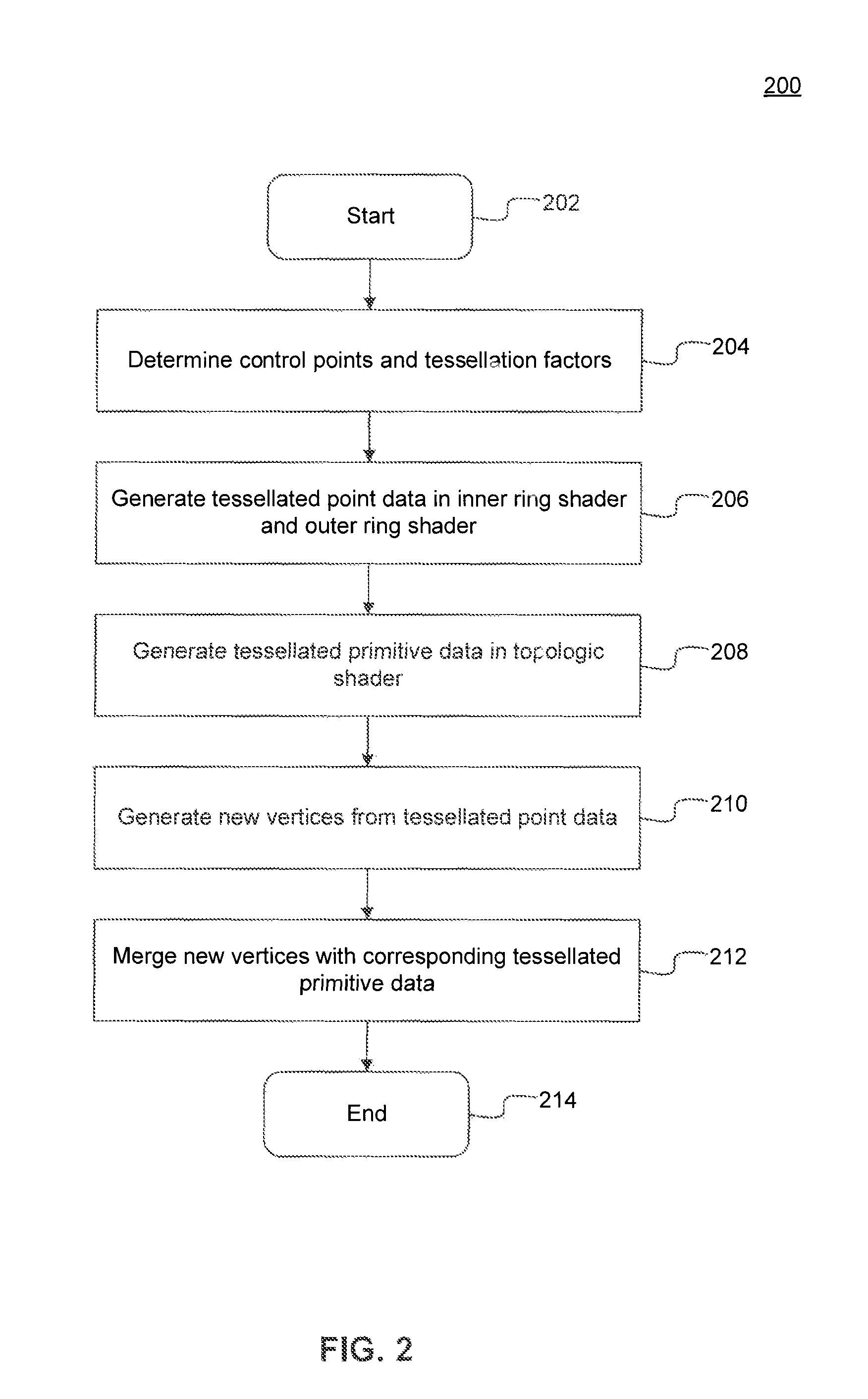
[0014]Embodiments of the invention, under certain circumstances, include a method comprising processing a patch, by a computing device, to identify an inner ring, an outer edge, and a stitch of the patch, computing point data using the inner ring and the outer edge, computing primitive data using the stitch, and combining the primitive data and point data to produce tessellated primitives of the patch.

[0015]Embodiments of the invention additionally include a computer-readable storage device having instructions stored thereon, execution of which, by a computing device, causes the computing device to perform operations comprising processing a patch to identify an inner ring, an outer edge, and a stitch of the patch, computing point data using the inner ring and the outer edge, computing primitive data using the stitch, and combining the primitive data and point data to produce tessellated primitives of the patch.

[0016]Embodiments of the invention farther include a system comprising a ...


PUM


Abstract

A system, method, and computer program product are provided for tessellation using shaders. New graphics pipeline stages implemented by shaders are introduced, including an inner ring shader, an outer edge shader, and topologic shader, which work together with a domain shader and geometry shader to provide tessellated points and primitives. A hull shader is modified to compute values used by the new shaders to perform tessellation algorithms. This approach provides parallelism and customizability to the presently static tessellation engine implementation.

Description

CROSS-REFERENCE TO RELATED APPLICATIONS[0001]The present application claims the benefit of U.S. Provisional Patent Application No. 61 / 581,879, filed Dec. 30, 2011, entitled “Accelerated Compute Tessellation by Compact Topological Data Structure”, which is incorporated herein by reference in its entirety.BACKGROUND OF INVENTION[0002]1. Field of the Invention[0003]The present invention relates generally to computer processing and, in particular, to tessellation techniques.[0004]2. Description of the Background Art[0005]As graphics processing computational power has dramatically increased in recent years, many software developers have taken advantage of these capabilities to develop photo-realistic applications. These applications tax modern system resources to the limit, requiring significant memory space to buffer vertex information defining three-dimensional (3D) models and their texture data, as well as graphics processing unit (GPU) clock cycles for their manipulation.[0006]Defini...

Claims


Application Information

Patent Timeline
Patent Type & Authority Patents(United States)
IPC IPC(8): G06T15/30G06T15/08G06T17/20G06T15/04
CPCG06T15/08G06T15/04G06T17/20G06T17/205
Inventor YANG, JIANZHU, HUAIBINGGOEL, VINEETLI, YAN
Owner ADVANCED MICRO DEVICES INC
Learn More