Camera washing device for camera lens
a technology for washing devices and cameras, applied in vehicle cleaning, vehicle maintenance, transportation and packaging, etc., can solve the problem that the driver of a motor vehicle cannot see the image detected, and achieve the effect of reducing the entire water consumption and reducing the time required to inject water particles
- Summary
- Abstract
- Description
- Claims
- Application Information
AI Technical Summary
Benefits of technology
Problems solved by technology
Method used
Image
Examples
first exemplary embodiment
[0036]A description will be given of the camera washing device for an in-vehicle camera according to a first exemplary embodiment of the present invention.
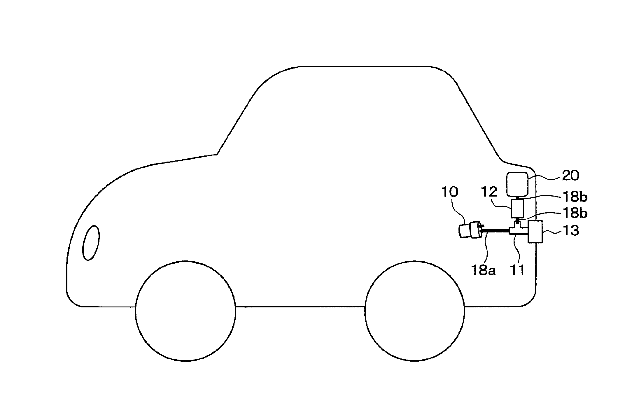
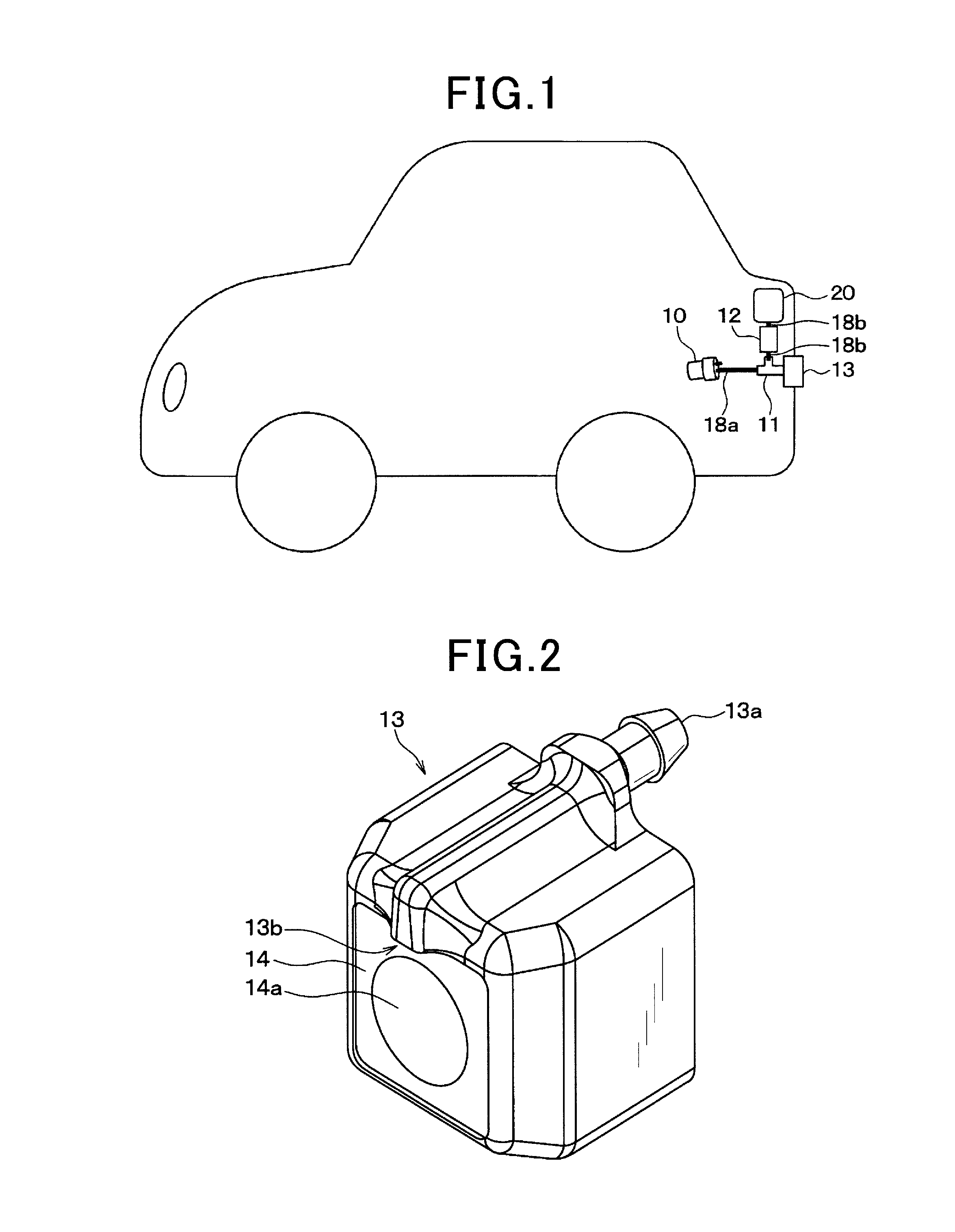
[0037]FIG. 1 is a schematic view showing an entire structure of the camera washing device for the in-vehicle camera according to the first exemplary embodiment of the present invention.
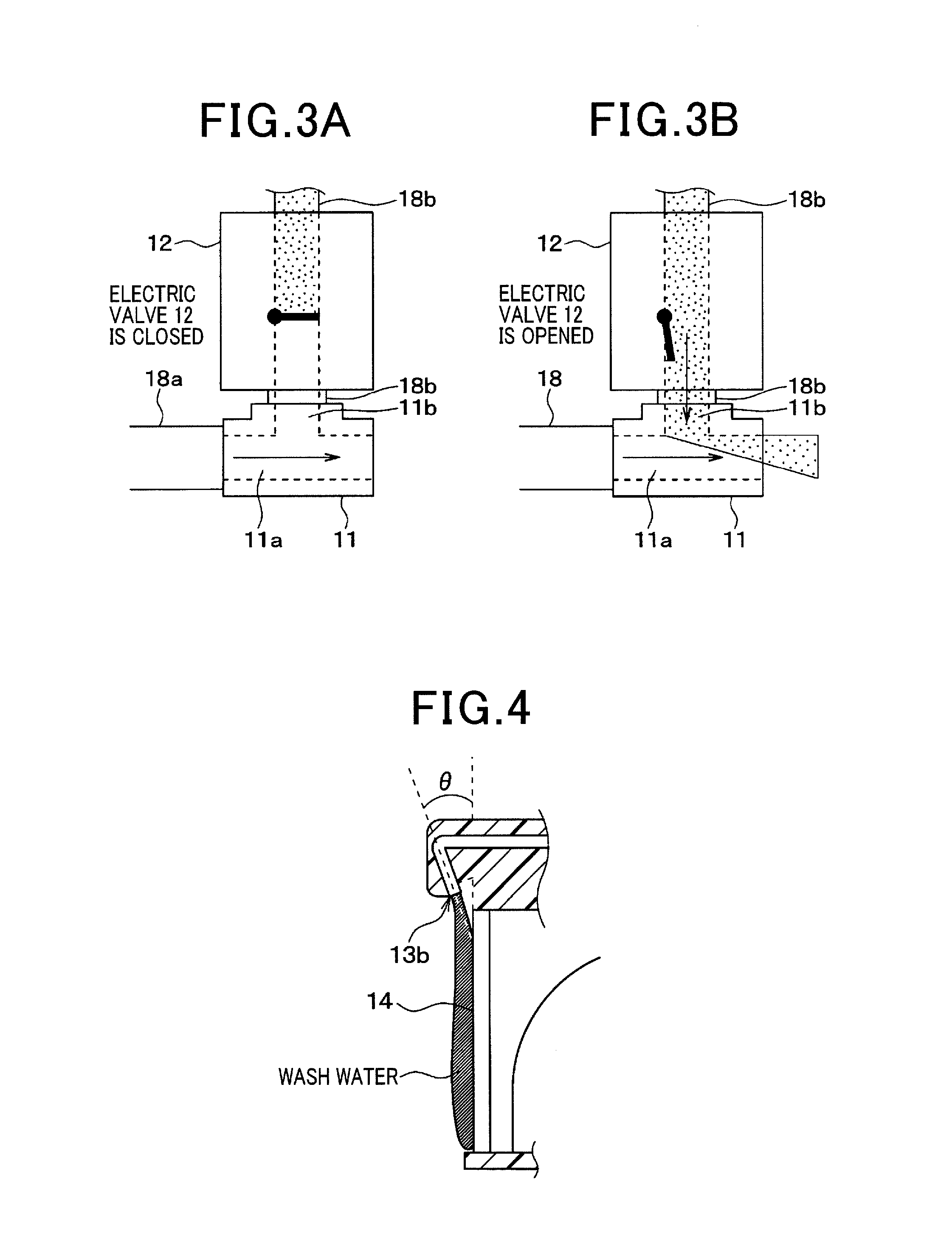
[0038]As shown in FIG. 1, the camera washing device according to the first exemplary embodiment has an air pump 10, a junction joint 11, an electromagnetic valve 12 (as the open-close part used in the claims), an injection nozzle 13, and a high-pressure air pipe 18a and a wash water pipe 18b, etc.
[0039]The injection nozzle 13 is equipped with a built-in rear camera 14. The rear camera 14 will be described later in detail with reference to FIG. 2.
[0040]The electromagnetic valve 12 is connected to a wash water tank 20. The wash water tank 20 stores wash water such as water only, rinse water or a water-detergent mixture.
[0041]For example, the camera wa...
second embodiment
[0102]Next, a description will be given of the camera washing device according to the second exemplary embodiment of the present invention with reference to FIG. 11 and FIG. 12.
[0103]FIG. 11 is a schematic view showing an entire structure of the camera washing device for an in-vehicle camera according to the second exemplary embodiment of the present invention.
[0104]The same components between the first exemplary embodiment shown in FIG. 1 and the second exemplary embodiment shown in FIG. 11 will be referred with the same reference numbers and characters. The explanation of the same components is omitted here for brevity.
[0105]As previously described, the camera washing device according to the first exemplary embodiment has the structure in which the wash water tank 20 is arranged at a position which is higher than the position of the electromagnetic valve 12. In this structure, the wash water stored in the tank flows into the high-pressure air passage 11a through the wash water pip...
third embodiment
[0111]Next, a description will be given of the camera washing device according to the third exemplary embodiment of the present invention with reference to FIG. 13 and FIG. 14.
[0112]FIG. 13 is a schematic view showing an entire structure of the camera washing device for an in-vehicle camera according to the third exemplary embodiment of the present invention;
[0113]The same components between the first exemplary embodiment shown in FIG. 1 and the third exemplary embodiment shown in FIG. 13 will be referred with the same reference numbers and characters. The explanation of the same components is omitted here for brevity.
[0114]As previously described, the camera washing device according to the first exemplary embodiment has the structure shown in FIG. 1 in which the wash water tank 20 is arranged at a position which is higher than the position of the electromagnetic valve 12 and the wash water stored in the wash water tank 20 flows into the high-pressure air passage 11a through the was...
PUM
 Abstract
Description
Claims
Application Information
 - R&D
- Intellectual Property
- Life Sciences
- Materials
- Tech Scout
- Unparalleled Data Quality
- Higher Quality Content
- 60% Fewer Hallucinations
Browse by: Latest US Patents, China's latest patents, Technical Efficacy Thesaurus, Application Domain, Technology Topic, Popular Technical Reports.
© 2025 PatSnap. All rights reserved.Legal|Privacy policy|Modern Slavery Act Transparency Statement|Sitemap|About US| Contact US: help@patsnap.com


