
Vehicle independent suspension

a suspension and independent technology, applied in the field of vehicle independent suspensions, can solve the problems of reduced ability to differentiate the toe change response of the suspension, low performance of the macpherson architecture in terms of load absorption, and low kinematic performance of the macpherson architecture, so as to improve comfort and improve longitudinal compliance , the effect of reducing longitudinal complian

Active Publication Date: 2015-11-03
SISTEMI SOSPENSIONI SPA
View PDF21 Cites 4 Cited by
  • Summary
  • Abstract
  • Description
  • Claims
  • Application Information

AI Technical Summary

Benefits of technology

The controlled degree of freedom provided by this suspension design results in improved comfort and reduced braking response time, which leads to improved vehicle stability. The suspension has greater toe change control and can provide different responses to traction and braking. Additionally, the design allows for a simpler and less expensive lower control arm.

Problems solved by technology

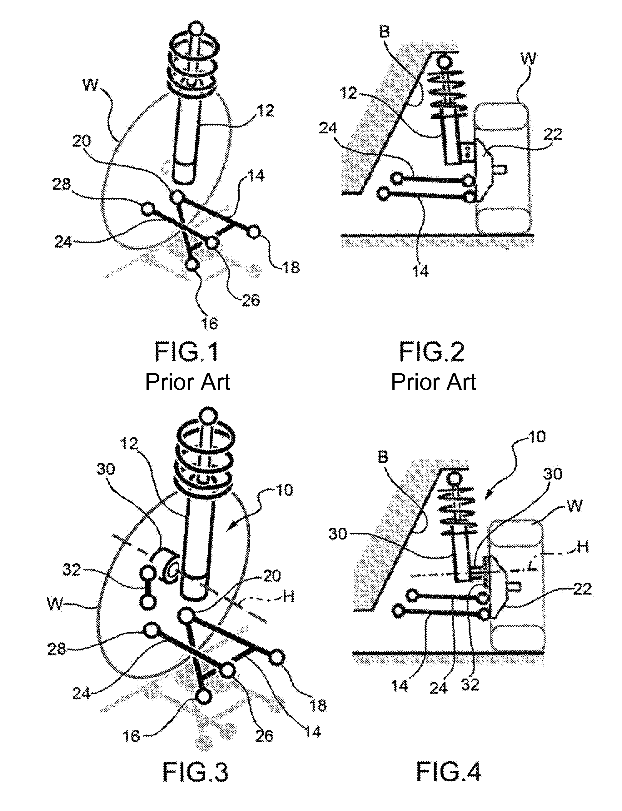
The MacPherson architecture suffers however from the drawback of having low kinematic performances, with regard in particular to the camber change during the bump / rebound motion of the wheel.
The performances of the MacPherson architecture in terms of load absorption are low, in particular with regard to the longitudinal forces acting on the wheel in case of braking or impact.
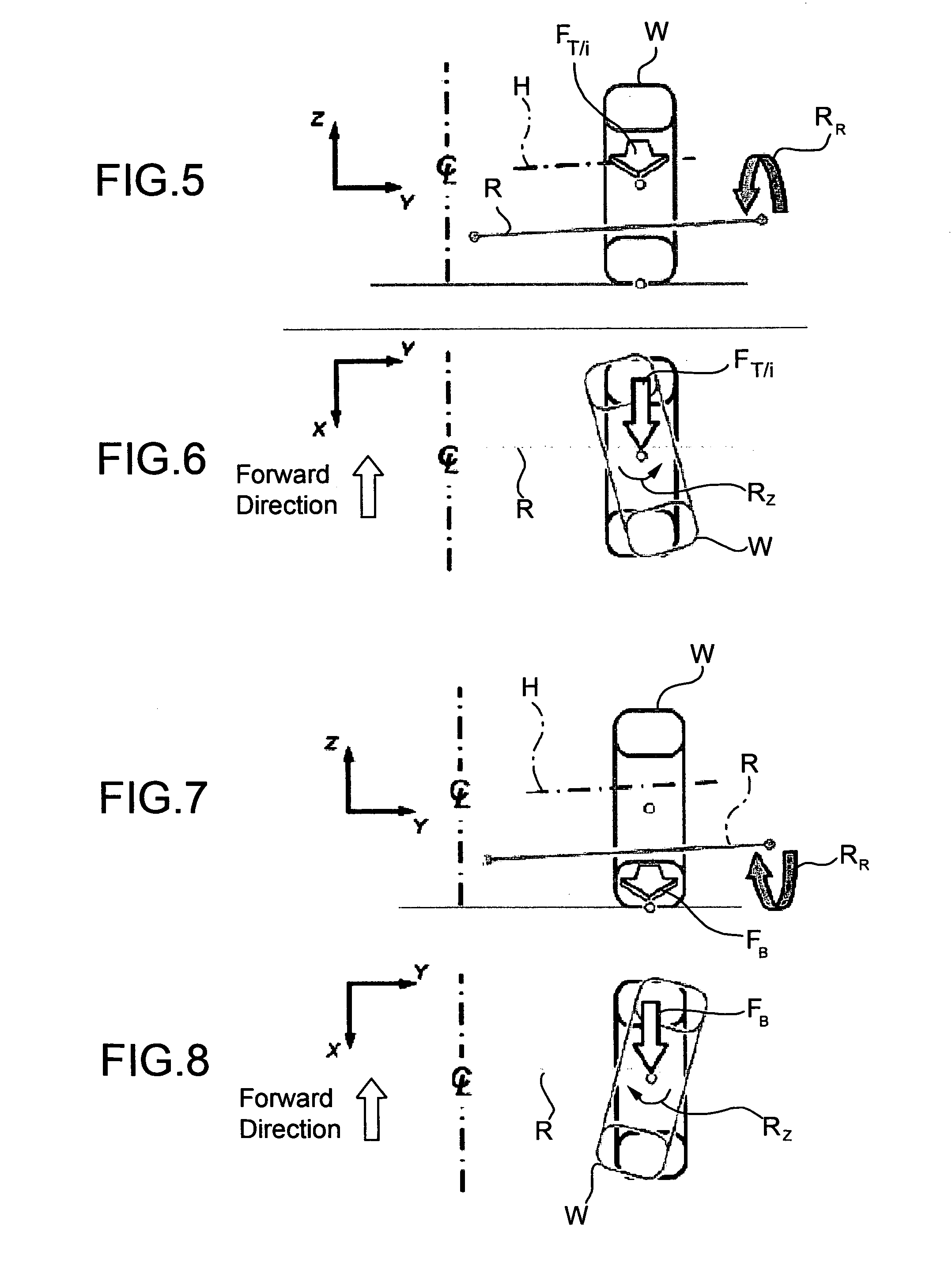
A further drawback of the MacPherson architecture is the reduced possibility to differentiate the toe change response of the suspension in traction and in braking Moreover, in the MacPherson architecture all the longitudinal compliance of the suspension is provided by the lower triangular arm, whose geometry is largely determined by the necessity to meet the requirement to combine high longitudinal compliance with high lateral stiffness, and therefore less freedom is left to the designer.
This has a detrimental effect on braking response.
Since all the longitudinal compliance is provided by the lower arm, the ball joint between the lower arm and the knuckle undergoes significant longitudinal displacements, which results directly in castor loss in braking and hence in loss of stability of the vehicle.

Method used


Image

  • Vehicle independent suspension
  • Vehicle independent suspension
  • Vehicle independent suspension

Examples


Embodiment Construction

[0042]In the following description and claims, terms such as “longitudinal” and “transverse”, “inner” and “outer”, “front” and “rear”, “upper” and “lower” etc. are to be intended as referred to the mounted condition of the suspension on the car.

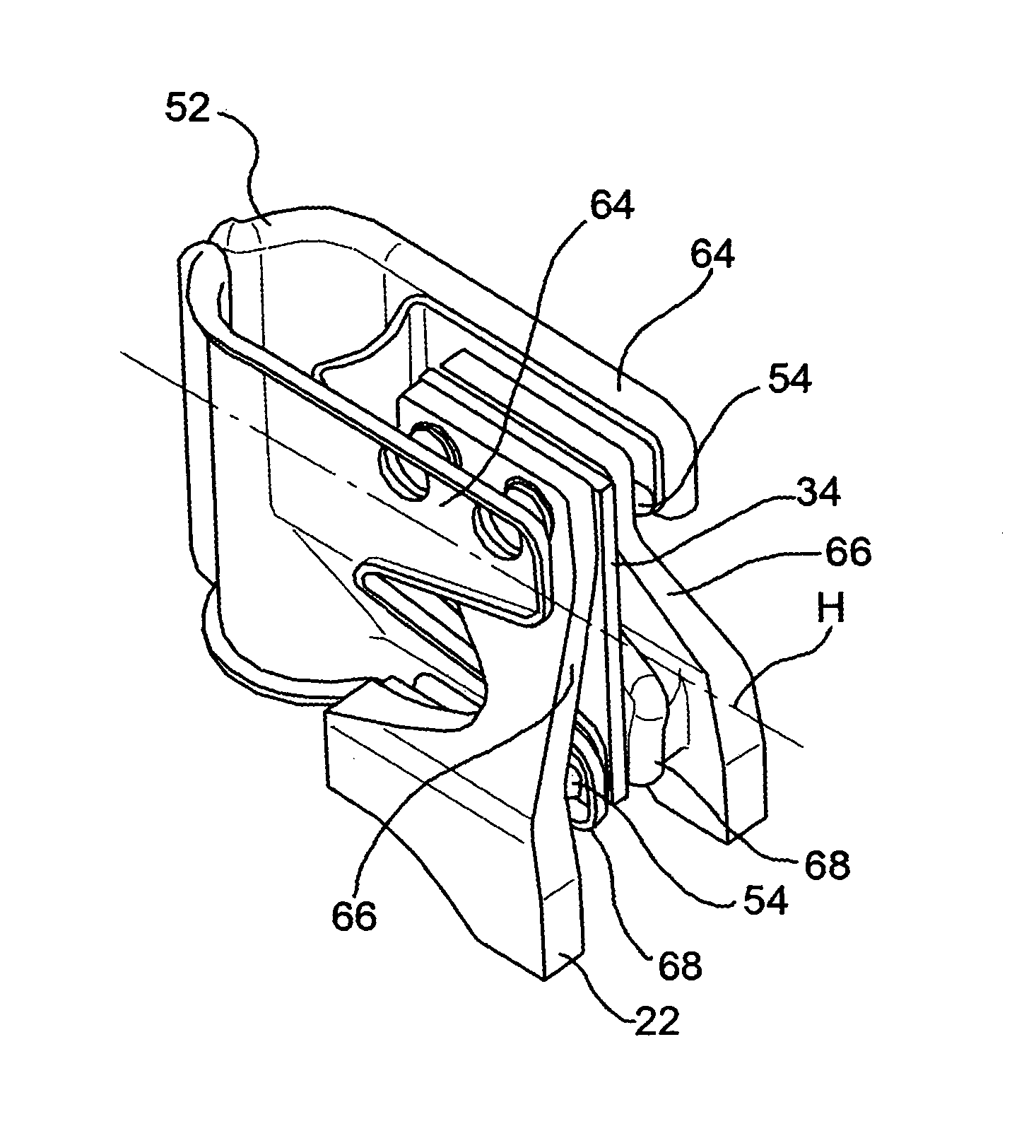
[0043]With reference first to FIGS. 3 and 4, where parts and elements identical or operatively equivalent to those of FIGS. 1 and 2 (prior art) have been given the same reference numerals, a motorcar front independent suspension is generally indicated 10 and basically includes a damper 12, a lower control arm 14, made in this embodiment as a triangular arm having a pair of transversely inner atttachment points 16 and 18 for articulated connection to the vehicle body (indicated “B” in FIG. 4) and a transversely outer attachment point 20 for articulated connection to a knuckle 22 for a wheel “W”, and a steering rod 24 having is transversely inner attachment point 26 for connection to the steering control mechanism and a transversely outer attac...


PUM


Abstract

An independent suspension (10) of a vehicle includes a knuckle (22) intended to carry a wheel (W), a damper (12) connected at a bottom end thereof to the knuckle (22), and a plurality of arms (14, 24) connected to a body (B) of the vehicle and the knuckle (22). A hinge device (30; 34) is interposed between the damper (12) and knuckle (22) to allow the damper (12) and knuckle (22) to rotate relative to each other about an axis of articulation (H) that is oriented to form an acute angle with a horizontal. A torsional stiffness control device (32; 34; 34, 70) is interposed between the damper (12) and knuckle (22) to control torsional stiffness of an articulated connection between the damper (12) and knuckle (22) about the axis of articulation (H).

Description

CROSS-REFERENCE TO RELATED APPLICATIONS[0001]This application claims benefit of PCT Patent Application PCT / IB2009 / 055003 entitled “Vehicle Independent Suspension” and filed on Nov. 11, 2009, which claims benefit of Italian Patent Application TO2008A000831 filed on Nov. 12, 2008.BACKGROUND OF INVENTION[0002]1. Field of Invention[0003]The invention relates, generally, to a vehicle independent suspension and, more particularly, to improvement of elasto-kinematic performance of the vehicle independent suspension architecture commonly known as “MacPherson architecture.”[0004]2. Description of Related Art[0005]The MacPherson suspension architecturt is fundamentally based on the idea of using the damper as an integrating part of the structure of the suspension. With referenceto FIGS. 1 and 2 of the attached drawings, which schematically show an example of vehicle front suspension accordnig to the MacPherson architecture, in perspective view and in front elevation, respectively, the suspens...

Claims


Application Information

Patent Timeline
Patent Type & Authority Patents(United States)
IPC IPC(8): B60G3/20B60G13/00B60G7/00
CPCB60G3/20B60G7/008B60G13/001B60G2200/14B60G2200/142B60G2200/156B60G2200/18B60G2200/462B60G2200/464B60G2204/129B60G2204/148
Inventor GERRARD, MILES BARNABY
Owner SISTEMI SOSPENSIONI SPA
Learn More