
Device and related method for dynamic traffic mirroring

a dynamic traffic and mirroring technology, applied in the field of computer-based networks, can solve the problems of insufficient data for all applications, network may not see all applications, etc., and achieve the effects of improving network manageability, security and efficiency of operation, and improving application identification capabilities

Active Publication Date: 2015-10-27
EXTREME NETWORKS INC
View PDF48 Cites 63 Cited by
  • Summary
  • Abstract
  • Description
  • Claims
  • Application Information

AI Technical Summary

Benefits of technology

[0018]The present invention includes an application identification function, a dynamic traffic mirroring function, a policy based dynamic mirroring function and a network system controller, all directed to improving network manageability, security and efficiency of operation. The application identification function carried out through an application identification engine, enables the determination or identification of the applications running in the network system through devices of the network infrastructure by snooping the flows of network traffic and making a characterization of the likely application associated with flows with a minimal amount of data in observed frames of received packets to do so. Signature languages have been leveraged in application fingerprinting products, but these languages were not in the past developed specifically for the purpose of application fingerprinting. The present invention takes advantage of intrusion detection languages for the purpose of fingerprinting applications with significant extensions to improve the application identification capabilities.

Problems solved by technology

Reliable application fingerprinting is best accomplished through this combination of both signature and heuristic processing, but there is an inherent conflict between the two techniques when both are applied simultaneously.
However, the network may not see all applications or enough data for all applications to effect sufficient training.

Method used


Image

  • Device and related method for dynamic traffic mirroring
  • Device and related method for dynamic traffic mirroring
  • Device and related method for dynamic traffic mirroring

Examples


Embodiment Construction

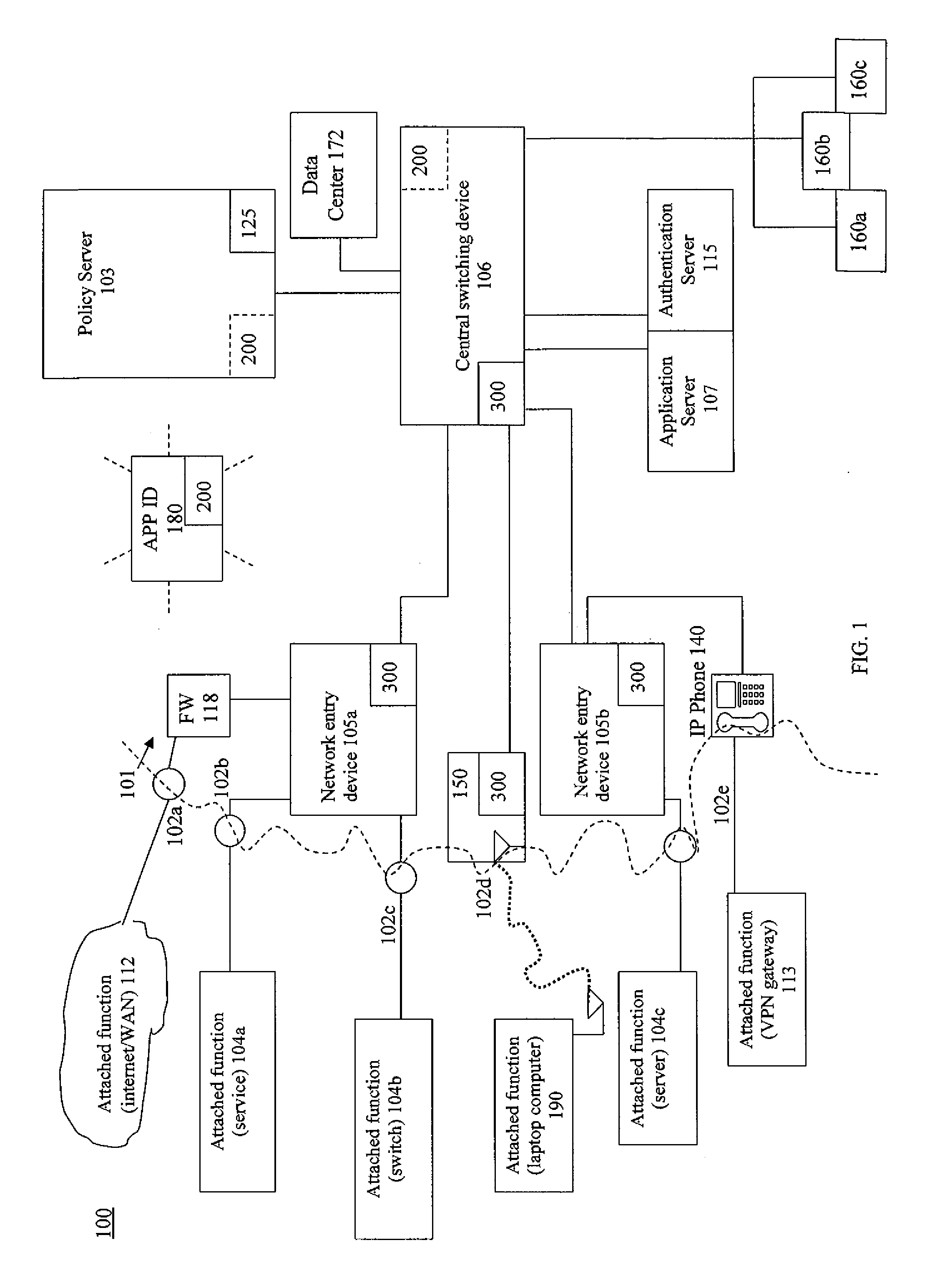
[0050]The devices and systems of the present invention are individual and connected hardware components including electrical elements, circuitry and functions embodied in those components. The hardware components are generally referred to as computing devices in that they combine physical hardware structures with software that may include firmware and middle ware for the purpose of executing instructions that produce the actions described herein. It is to be understood that the hardware devices that are network infrastructure devices defined herein represent computing devices suitable for executing the network functions described herein. Other types of computing devices may also be part of a network system of the present invention including such computing devices that perform network functions. Such other types of computing devices include laptops, tablets and mobile devices including smartphones, for example. It is to be understood that a computing device described herein may be an...


PUM


Abstract

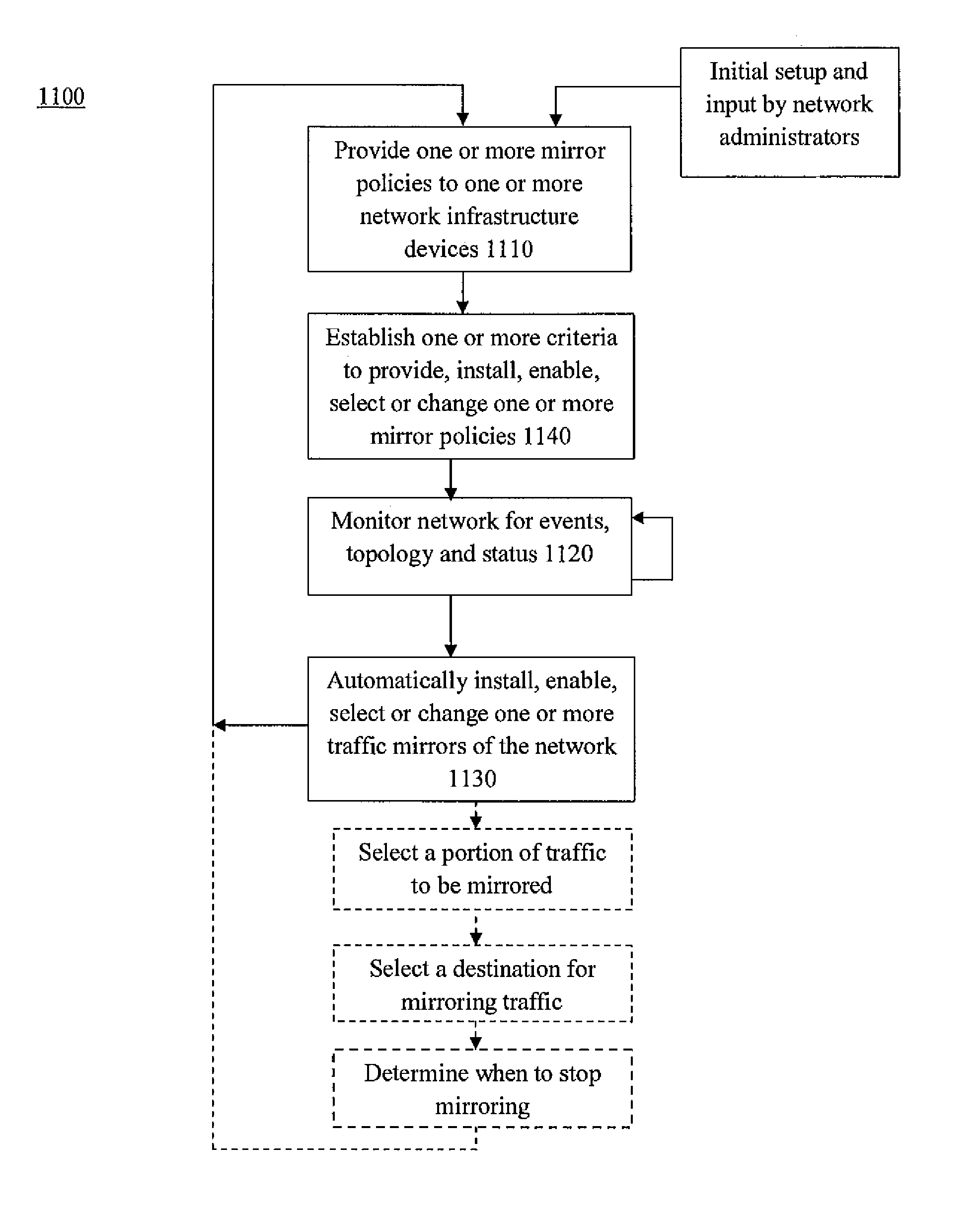
A function is provided in a network system for the dynamic mirroring of network traffic for a variety of purposes including the identification of characteristics of the traffic. Multiple criteria are established for when, what and where to mirror the traffic. The criteria include what frames of traffic to mirror, what portions of the selected frames to mirror, one or more portals through which to mirror the selected frames, a destination for the mirroring and the establishment of a mirror in a device to carry out the mirroring. The criteria may also include when to stop the mirroring. The mirroring instructions can be changed based on the detection of a triggering event, such as authentication, device type or status, ownership of an attached function attached to the device, flow status, but not limited to that. The function may be established in one or more devices of the network.

Description

CROSS REFERENCE TO RELATED APPLICATIONS[0001]This application is related to the following applications owned by a common assignee and all of which were filed on the same date as the present application. All are incorporated herein by reference. The related applications are identified by title and corresponding serial number as follows: A DEVICE AND RELATED METHOD FOR DYNAMIC TRAFFIC MIRRORING POLICY, Ser. No. 13 / 835,679, A DEVICE AND RELATED METHOD FOR ESTABLISHING NETWORK POLICY BASED ON APPLICATIONS, Ser. No. 13 / 836,048, A DEVICE AND RELATED METHOD FOR APPLICATION IDENTIFICATION, Ser. No. 13 / 836,195, A SYSTEM AND RELATED METHOD FOR NETWORK MONITORING AND CONTROL BASED ON APPLICATIONS, Ser. No. 13 / 836,371, and A DEVICE AND RELATED METHOD FOR SCORING APPLICATIONS RUNNING ON A NETWORK, Ser. No. 13 / 836,545.BACKGROUND OF THE INVENTION[0002]1. Field of the Invention[0003]The present invention relates to computer-based networks and their components. More particularly, the present inventi...

Claims


Application Information

Patent Timeline
Patent Type & Authority Patents(United States)
IPC IPC(8): H04L12/26H04L12/24
CPCH04L43/12H04L43/028H04L41/0213H04L67/1095
Inventor KJENDAL, DAVIDNISPEL, MARKUSEATON, ERNIEGRAHAM, RICHARDHASKELL, JEFFREY
Owner EXTREME NETWORKS INC
Learn More