Work vehicle coordinating system

a technology of coordinating system and turn-around, applied in the direction of process and machine control, distance measurement, instruments, etc., can solve the problem of difficult follow-up of turn-around, and achieve the effect of improving follow-up performance and speeding up the follow-up

Active Publication Date: 2015-10-20
KUBOTA LTD
View PDF2 Cites 10 Cited by
  • Summary
  • Abstract
  • Description
  • Claims
  • Application Information

AI Technical Summary

Benefits of technology

[0016]With the above-described configuration, when a ground work is to be carried out with repetition of a work traveling along a forward path and a work traveling along a reverse path across turn traveling at the opposed ends, the sub work vehicle is un-manned controlled by the steering control section, with using, as a control target, a target traveling position calculated for the work traveling with taking into consideration the ground working width of the main work vehicle and the ground working width of the sub work vehicle based on the position of the sub work vehicle itself and the traveling path of the preceding main work vehicle. With this, there is realized substantially a ground work with a ground working width adding up the ground working width of the main work vehicle and the ground working width of the sub work vehicle together. Taking a follow-up control error into consideration, there is set a certain amount of overlapping area between the ground working widths of the main work vehicle and the sub work vehicle. For the sub work vehicle during a turn traveling, the ground working width of the main work vehicle and the ground working width of the sub work vehicle need to be taken into consideration, without regards to its positional relationship with the main work vehicle or the traveling path of the main work vehicle during its turn traveling. In this regard, the sub work vehicle will be caused to travel, based on a turn traveling path calculated from a turn traveling start position and a turn traveling end position of the main work vehicle. Namely, a target traveling position will be calculated based on an appropriate turn traveling path not dependent on the traveling path of the main work vehicle, and the sub work vehicle is un-manned controlled with using this target traveling position. This eliminates such problem as a need for increasing the depth of the turning area more than necessary.
[0019]In order to improve the follow-up performance at the time of transition of a turn traveling to a work traveling of the sub work vehicle, according to one preferred embodiment of the present invention, ending of the turn traveling of the sub work vehicle is effected within the turning area, and follow-up by the sub work vehicle based on the work traveling path of the main work vehicle is effected before the work traveling. Namely, in this embodiment, speedy follow-up is made possible by effecting follow-up to the main work vehicle with stopping the turn traveling before a turning end position corresponding to the timing when the main work vehicle actually ends its turn traveling (a start point of a work traveling).
[0028]With this arrangement, the sub work vehicle needs only small design change, so this arrangement is advantageous for a system using a plurality of sub work vehicles.

Problems solved by technology

However, with the follow-up mode disclosed in e.g. U.S. Pat. No. 6,732,024 not taking turn traveling into consideration, follow-up of the turn traveling becomes difficult.

Method used


Image

  • Work vehicle coordinating system
  • Work vehicle coordinating system
  • Work vehicle coordinating system

Examples


Embodiment Construction

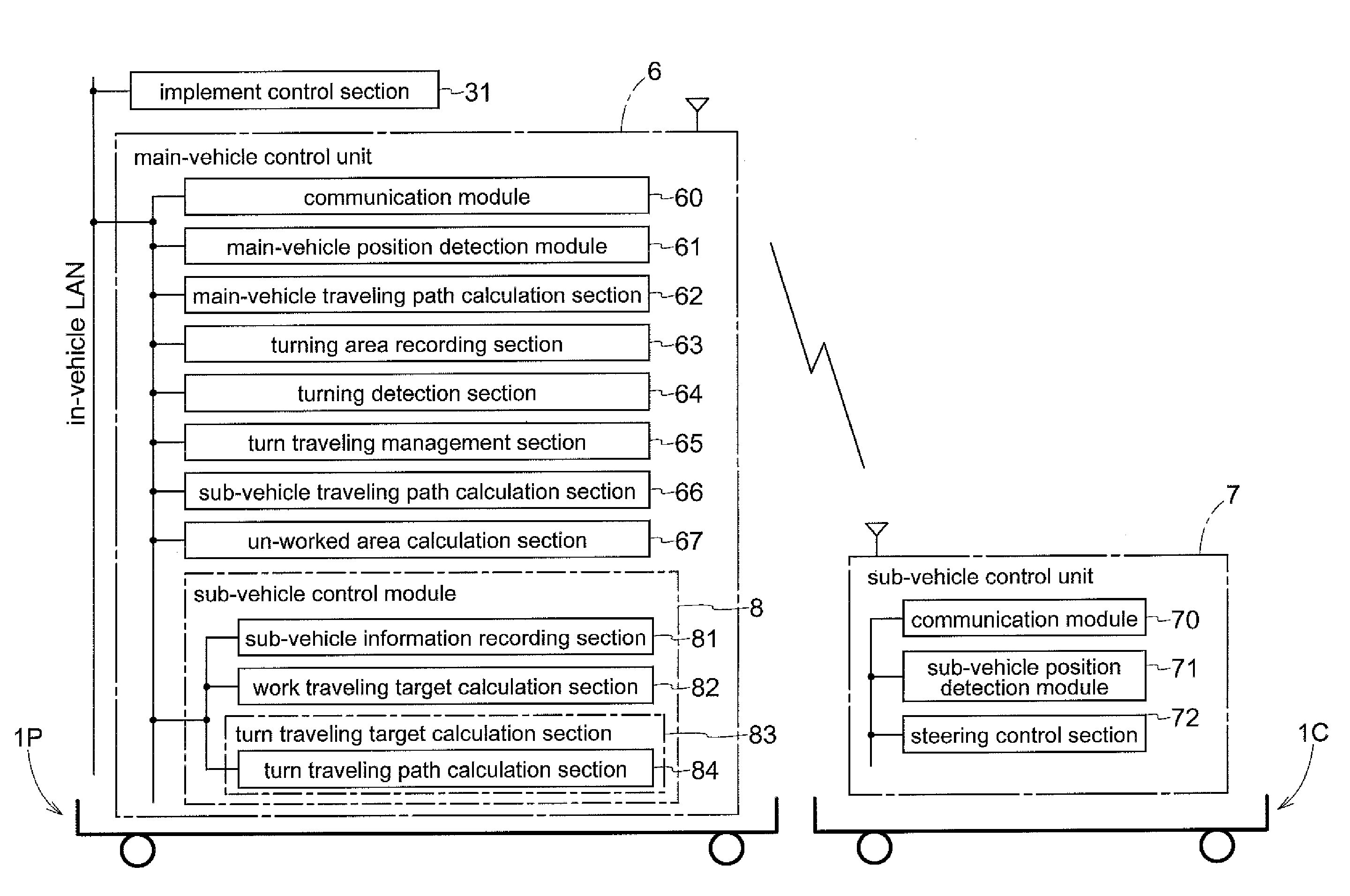
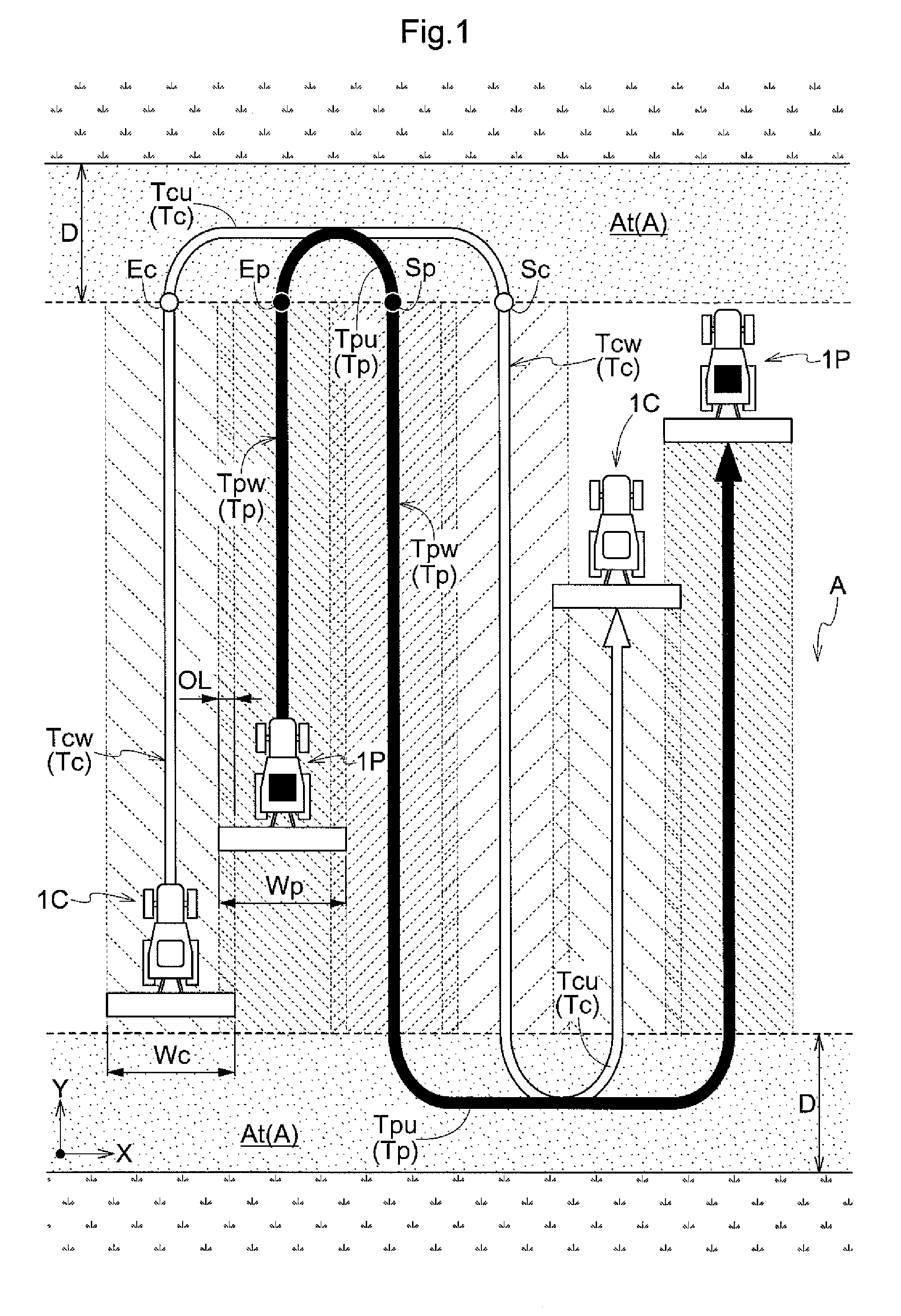
[0041]Before explaining a specific embodiment of a work vehicle coordinating system according to the present invention, its basic principle will be explained with reference to FIGS. 1 and 2. In this work vehicle coordinating system, a ground work is effected by a manned controlled type main work vehicle 1P and an un-manned controlled type sub work vehicle 1C that follows up (or follows) the main work vehicle 1P. In the example of work illustrated in FIG. 1, from the left rear side of the preceding main work vehicle 1P, the sub work vehicle 1C travels to track the main work vehicle 1P. A ground site to be worked is demarked by ridges. Basically, the ground work is implemented by forward and reverse straight traveling. So, firstly, a circumference traveling along the ridges is effected Then, a worked area created thereby becomes a turning area At for a turning (U-turn) effected between a forward traveling and a reverse traveling. In case a circumferential work is to be effected at the...


PUM


Abstract

Disclosed is a work vehicle coordinating system configured to carry out a ground work by a main work vehicle and an un-manned controlled sub work vehicle that follows up the main work vehicle. This system includes a main-vehicle position detection module, a sub-vehicle position detection module, a main-vehicle traveling path calculation section, a turning detection unit, a work traveling target calculation section, a turn traveling target calculation section, and a steering control section.

Description

CROSS REFERENCE TO RELATED APPLICATION[0001]This application claims priority to Japanese Patent Application No. 2013-050875 filed Mar. 13, 2013, the disclosure of which is hereby incorporated in its entirety by reference.BACKGROUND OF THE INVENTION[0002]1. Field of the Invention[0003]The present invention relates to a work vehicle coordinating system configured to carry out a ground work by a main work vehicle and an un-manned controlled sub work vehicle that follows up the main work vehicle.[0004]2. Description of the Related Art[0005]From U.S. Pat. No. 6,052,647, there is known a vehicle control system configured to determine target traveling positions one after another based on actual traveling positions of a main work vehicle and to control a sub work vehicle toward the respective target traveling positions. In this vehicle control system, there are disclosed e.g. a control mode causing the sub work vehicle to follow the main work vehicle in such a manner to maintain offset amou...

Claims


Application Information

Patent Timeline
Patent Type & Authority Patents(United States)
IPC IPC(8): G01C22/00G05D1/02G05D1/00
CPCG05D1/0287G05D1/0295G05D2201/0201
Inventor MATSUZAKI, YUSHIARAKI, HIROYUKIUOYA, YASUHISASUZUKAWA, MEGUMITAKADA, FUMIO
Owner KUBOTA LTD
Why Eureka
Try Eureka