
Wave suppressor and sediment collection system

a sediment collection system and wave suppressor technology, applied in the direction of piers, land reclamation, groynes, etc., can solve the problems of easy erosion, loss of valuable coastline, etc., to stop the erosion of newly deposited material, stop polluting and contaminating areas, and maximize sediment recovery

Active Publication Date: 2015-10-13
PIERCE JR WEBSTER
View PDF30 Cites 14 Cited by
  • Summary
  • Abstract
  • Description
  • Claims
  • Application Information

AI Technical Summary

Benefits of technology

[0017]In another embodiment, the system as described above would include a secondary system stationed in the water ahead of the system, which would include one or multiple barges, each barge having an air compressor system, preferably powered by wind and solar energy, to buildup compressed air in tanks, and upon water reaching a certain level, automatically releasing the compressed air through openings at the ends of a plurality of air lines which would be able to rove along the water bottom, resulting in the pressurized air stirring and fluffing up sand and silt from the water bottom. This would provide a great amount of additional sand and silt becoming suspended in the water and being carried through the land restoration system and deposited between the system and the coastline, thus greatly increasing the amount of sediment built up between the system and the coastline.
[0030]It is a further principal object of the present invention to provide a system which will be constructed and applied in such a way as to have no adverse effect of the ecology of the environment the WSSC System is placed into.

Problems solved by technology

The loss of valuable coastline for states along the Gulf of Mexico, Atlantic Ocean and Pacific Ocean is a very serious problem.
However, with the loss of valuable marsh grass, the soil became susceptible to erosion, and consequently miles of valuable coastline were lost.
It is estimated that coastal erosion by the flow of the tides on a daily basis results in a loss of many square miles of coastline.
Furthermore, the reduction in the marsh land has resulted in the reduction of protection from hurricane storm surge and wind velocity.

Method used


Image

  • Wave suppressor and sediment collection system
  • Wave suppressor and sediment collection system
  • Wave suppressor and sediment collection system

Examples


first embodiment

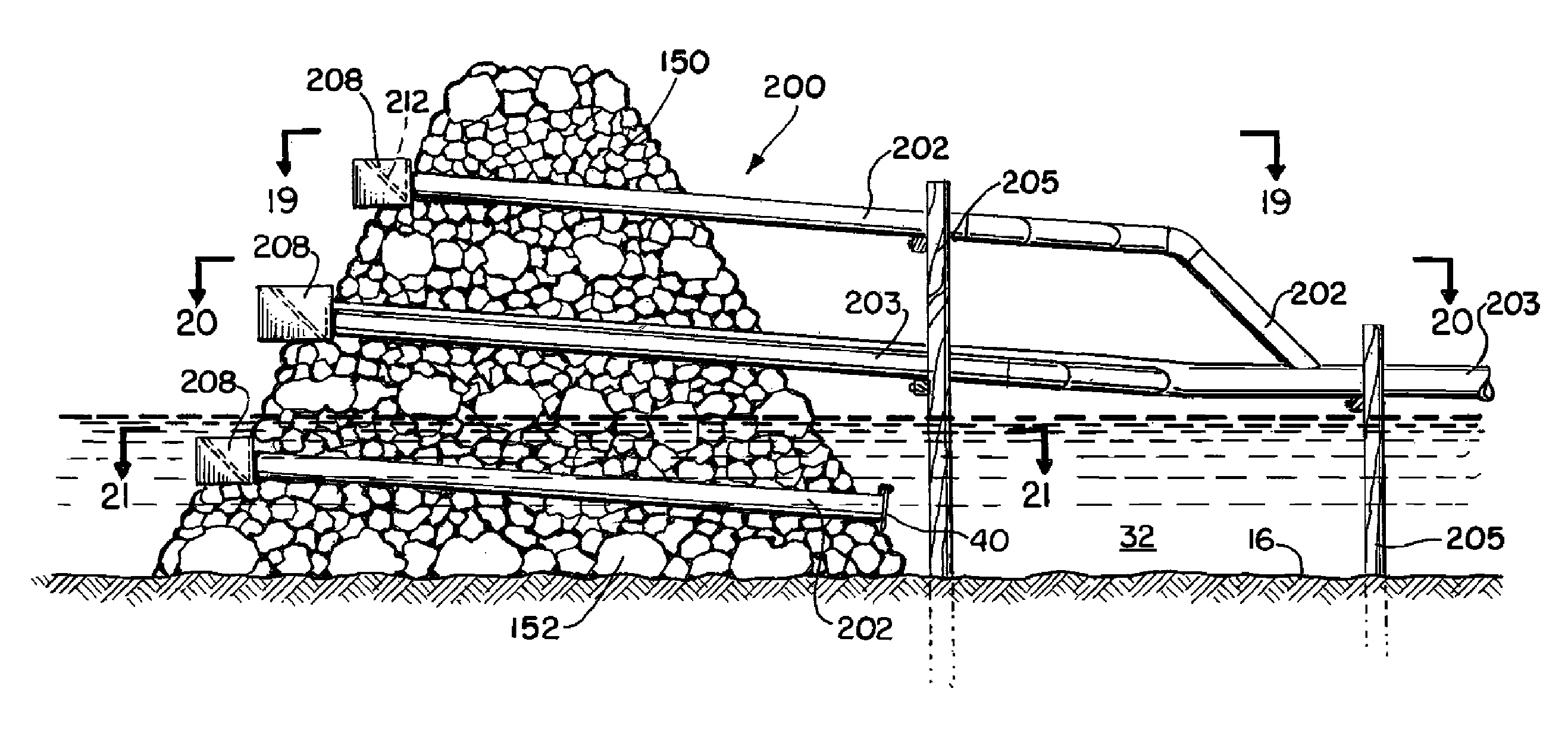
[0075]Reference is now made to FIGS. 18 through 24, where the WSSC System, labeled System 200 is incorporated into a rock jetty 150, of the type which has been constructed to block the entrance to the waterway referred to as Mr. Go in South Louisiana. As illustrated in top views in FIGS. 19 through 21, there is provided a rock jetty 150 into which the system 200 is incorporated. In FIG. 21, taken along lines 21-21 in FIG. 18, it is foreseen that the base 152 of the jetty 150 would be laid in place, and then a plurality of elongated pipes 202 would extend from the forward point 156 of jetty 150, in this case three pipe sections 202 to the rear point 158 of rock jetty 150. At the forward point 156, the three pipes 202 would extend from a trough 208, as illustrated in FIG. 24, having an upright rear wall 210, a angulated floor 212, and a pair of side walls 214, so that the trough 208 would serve to capture the flow or water 32 carrying sediment 34, and the angulated floor 212 would dir...

second embodiment

[0081]Reference is now made to FIGS. 26A-33C, which illustrate the WSSC System as it would be installed through a rock jetty 150 and will be illustrated as WSSC System 300.

[0082]Turning now to FIGS. 26A and 26B, there is illustrated a body of water 60 having a current illustrated by arrows 65, flowing towards a rock jetty 150 as illustrated. In FIG. 27 there is a plurality of sediment collection components 302, which will be described below, positioned through the rock jetty 150 for the reasons as will be described further. As illustrated more clearly in FIG. 27, there is provided a single sediment collection component 302, extending through a rock jetty 150. The principal function of each of the components 302 is to receive water and sediment through the component 302 from the unprotected side 151 of the jetty 150 to the protected side 153 of the jetty 150 in order to enable sediment to be carried through the components 302 from the unprotected side 151 of the jetty 150, to the pro...


PUM


Abstract

A system and method to provide water and sediment flow through a rock jetty, which includes a plurality of collection components mounted along a forward face of the rock jetty, each collection component having a plurality of flow pipes to receive water carrying sediment; a principal flow pipe to receive flow from the plurality of flow pipes and to carry water and sediment a predetermined distance to deposit at the rear of the jetty; a continuous trough mounted on the jetty forward face to efficiently capture water and sediment at entrances of the plurality of flow pipes; and a filter screen covering the entrance of the trough to allow water and sediment to flow into the trough and to prevent large rocks and other debris from entering. Sections of principal flow pipe may be removed when sufficient quantity of sediment has been deposited, so that additional sediment can be deposited.

Description

CROSS-REFERENCE TO RELATED APPLICATIONS[0001]This is a continuation-in-part of U.S. patent application Ser. No. 12 / 576,359, filed 9 Oct. 2009 (issuing as U.S. Pat. No. 8,226,325 on 24 Jul. 2012), by the same inventor, incorporated herein by reference thereto.[0002]Priority of U.S. patent application Ser. No. 12 / 576,359, filed 9 Oct. 2009, which is incorporated herein by reference, is hereby claimed.[0003]International Application Serial No. PCT / US2010 / 052182, filed 11 Oct. 2010, which was published on 14 Apr. 2011 and bears Publication No. WO2011 / 044556, is hereby incorporated herein by reference.STATEMENT REGARDING FEDERALLY SPONSORED RESEARCH OR DEVELOPMENT[0004]Not applicableREFERENCE TO A “MICROFICHE APPENDIX”[0005]Not applicableBACKGROUND OF THE INVENTION[0006]1. Field of the Invention[0007]The present invention relates to protection from coastline erosion caused by wave action or tidal surge and the restoration of coastline lost from such wave action or tidal surge activity. M...

Claims


Application Information

Patent Timeline
Patent Type & Authority Patents(United States)
IPC IPC(8): E02B3/06E02B3/04
CPCE02B3/04E02B3/06Y02A10/11E02B3/08E02B3/18E02B7/02E02B8/00
Inventor PIERCE, JR., WEBSTER
Owner PIERCE JR WEBSTER
Learn More