
Apparatus and method for controlling a multi-fuel engine

a multi-fuel engine and control apparatus technology, applied in the direction of brake action initiation, braking system, position/direction control, etc., can solve the problems of high cost and time-consuming of above conversion, and achieve the effect of reducing the supply, improving the economy of a dual-fuel engine, and reducing the supply of primary fuel

Active Publication Date: 2015-09-29
INTELLIGENT DIESEL SYST
View PDF23 Cites 4 Cited by
  • Summary
  • Abstract
  • Description
  • Claims
  • Application Information

AI Technical Summary

Benefits of technology

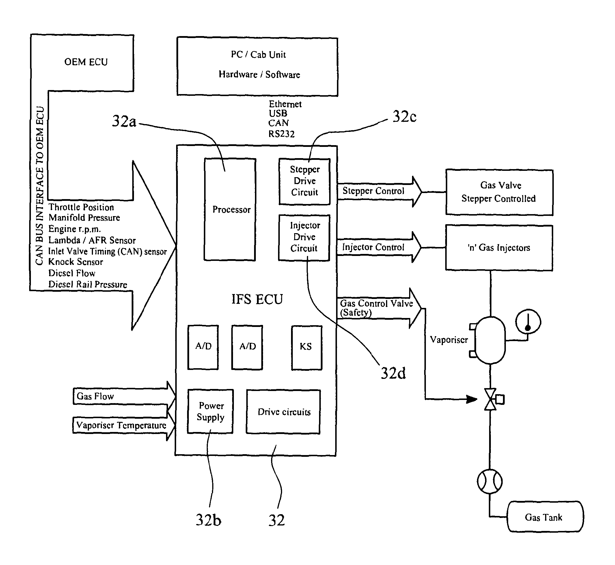
The present invention provides a dual fuel engine with a primary fuel supply and a secondary fuel supply that mix with air for combustion. The supply of both fuels may be actively managed based on the engine performance characteristic or economy of performance. The management may involve controlling the injection timing, pressure, and throttle of the primary fuel, as well as actively reducing the supply of primary fuel when secondary fuel is supplied. The invention also includes a method of improving the economy of a dual fuel engine by actively managing the supply of both fuels. The primary and secondary fuels may be injected into the cylinders either in gaseous state through an open air inlet valve or directly into the cylinder. The technical effects of the present invention are improved engine performance and efficiency with reduced fuel consumption and emission control.

Problems solved by technology

The above conversion can be expensive and time-consuming not least because of the number of devices which must be installed.

Method used


Image

  • Apparatus and method for controlling a multi-fuel engine
  • Apparatus and method for controlling a multi-fuel engine
  • Apparatus and method for controlling a multi-fuel engine

Examples


first embodiment

[0055]FIG. 5 shows the same cycle, with the same reference numerals representing the same elements as in FIG. 4, but with the difference that a gas injector 82 injects gas, as a secondary fuel, in the region of the inlet manifold 68 immediately upstream of the inlet valve 64 in accordance with the present invention. As can be seen from the timing information at the bottom of the diagram the said region of the inlet manifold is fumigated—i.e. a charge of gas is deposited—continuously throughout the four strokes. The gas mixes with the air and is drawn into the cylinder when the inlet valve is open, from slightly before 0 degrees until slightly after 180 degrees.

second embodiment

[0056]In the present invention, the gas supply nozzle is located closer to the inlet valve and is oriented towards the interior of the cylinder. In this embodiment, as well as fumigating the region of the inlet manifold outside the valve while the valve is closed, the gas supply nozzle is arranged to inject gas into the cylinder through the inlet valve 64 during the brief period when the valve 64 is open.

[0057]This arrangement allows a greater control of the mixing of the gas with the air. In particular, it ensures that a known quantity of gas is delivered precisely to where it needs to be to mix completely with the air.

[0058]FIG. 6 shows the same cycle as FIGS. 4 and 5, with the same reference numerals representing the same elements as in those figures, but with the difference that the gas injector 82 is directed towards the inlet valve 64 in accordance with the second embodiment of the present invention. The timing information at the bottom of the diagram illustrates that, for at ...


PUM


Abstract

A dual-fuel engine has a primary fuel supply and a secondary fuel supply, the primary and secondary fuels being arranged in use to mix with each other and with air for combustion in one or more cylinders of the engine. The supply of both the primary and secondary fuels is arranged to be actively managed in accordance with a desired engine performance characteristic by an electronic controller. In one arrangement the supply of a primary fuel is arranged to be actively reduced when a secondary fuel is supplied to the engine.

Description

CROSS-REFERENCE TO RELATED APPLICATIONS[0001]This application is the United States National Phase of PCT Patent Application No. GB2010 / 050718 filed on 30 Apr. 2010, which claims priority to British Patent Application No. 0907614.2 filed 1 May 2009, both of which are incorporated herein by reference.BACKGROUND OF THE INVENTION[0002]The present invention relates to the control of multi-fuel engines and is concerned particularly, although not exclusively, with apparatus and a method for controlling a dual fuel engine, such as a diesel / gas engine.[0003]Multi-fuel engines, i.e. engines which use more than one type of fuel, have been known for many years. One successful type of multi-fuel engine is the dual fuel engine which uses diesel oil as a base, or primary fuel, and either liquid petroleum gas (LPG), compressed natural gas (CNG) or liquefied natural gas (LNG) as an alternative or secondary fuel. Secondary fuels are often attractive because of their low cost compared to diesel oil. S...

Claims


Application Information

Patent Timeline
IPC IPC(8): F02D19/10F02D19/08F02D41/00F02B7/08F02D19/06
CPCF02D19/10F02B7/08F02D19/061F02D19/0647F02D19/0692F02D19/081F02D41/0027F02B2201/064F02D2400/11Y02T10/36Y02T10/30
Inventor FINN, PAUL HOWARDHORLER, GREGORY DOUGLAS
Owner INTELLIGENT DIESEL SYST
Learn More