
Cutter assembly

a cutter and assembly technology, applied in the field of cutter assembly, can solve the problems of user injury, laborious, and time-consuming to replace the conventional cutter assembly with a new one, and achieve the effect of saving time and labor

Active Publication Date: 2015-09-29
MIYANACH IND
View PDF5 Cites 3 Cited by
  • Summary
  • Abstract
  • Description
  • Claims
  • Application Information

AI Technical Summary

Benefits of technology

Facilitates rapid and secure head replacement, enhancing safety and reducing storage and usage costs by allowing a single adapter to be used with multiple heads of varying sizes, thereby improving operational efficiency.

Problems solved by technology

Therefore, to replace the conventional cutter assembly with a new one takes time and is laborious.
Furthermore, during the process of replacing the conventional cutter assembly, tools, the detached cutter assembly and the new cutter assembly have to be held by the user such that these components easily fall off from the user to cause injury to the user.

Method used


Image

  • Cutter assembly
  • Cutter assembly
  • Cutter assembly

Examples


Embodiment Construction

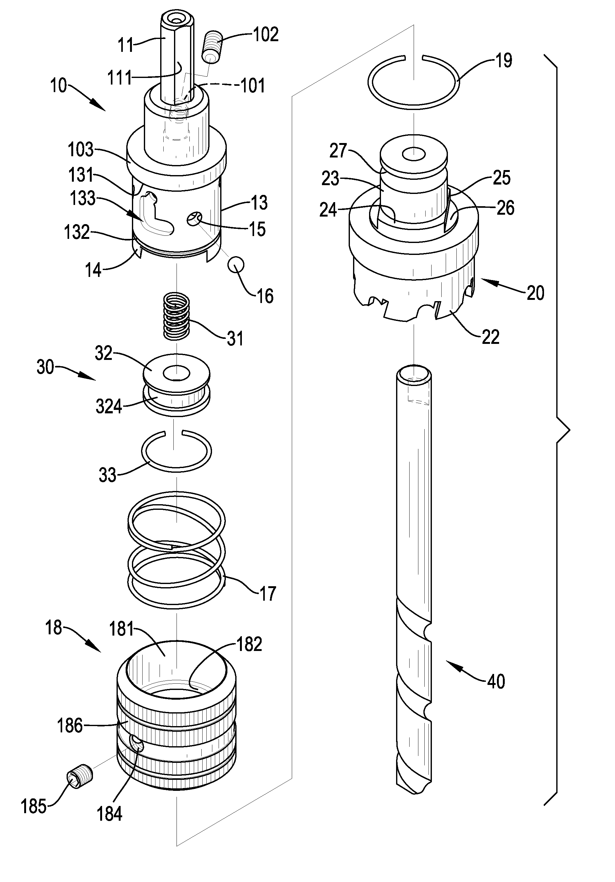
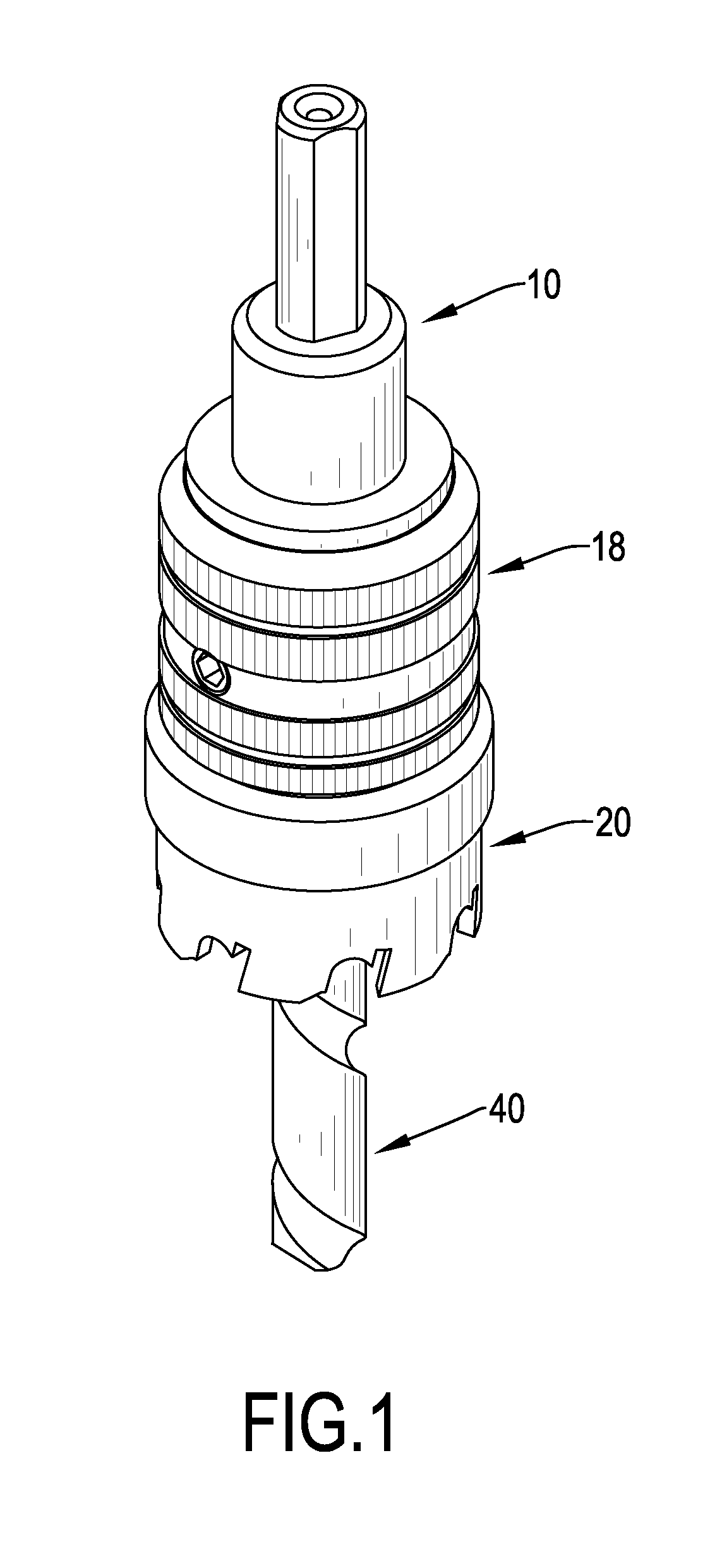
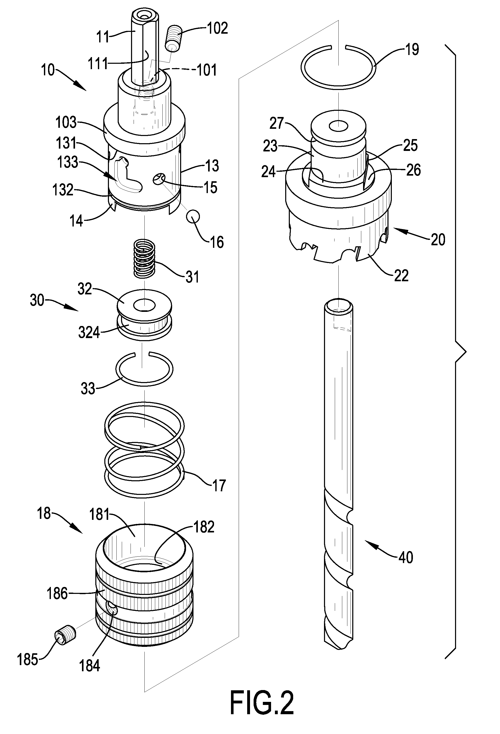
[0020]With reference to FIGS. 1 to 3, a cutter assembly in accordance with the present invention comprises an adapter 10, an outer collar 18, a recoil spring 17, a head 20, a pushing assembly 30 and a central drill 40.

[0021]The adapter 10 has two ends, a connecting rod 11, an inserting hole 12, a central hole 121, a sleeve segment 13, a flange 103, a guiding slot 133, at least one holding tab 14, multiple ball holes 15 and multiple balls 16. The connecting rod 11 and the inserting hole 12 are formed respectively on two ends of the adapter 10. The connecting rod 11 is formed on one end of the adapter 10 and has three clamping surfaces 111 formed on the connecting rod 11 at even intervals, such that the connecting rod 11 can be clamped securely with a clamping device of a rotating machine via the clamping surfaces 111. The inserting hole 12 is defined in the other end of the adapter 10 opposite to the connecting rod 11. The central hole 121 is defined in the adapter 10 and co-axially ...


PUM

PropertyMeasurementUnit
diameteraaaaaaaaaa
movement rangeaaaaaaaaaa
outer diameteraaaaaaaaaa

Abstract

A cutter assembly has an adapter, an outer collar, a recoil spring, a head, a pushing assembly and a central drill. The adapter has an L-shaped guiding slot and multiple balls. The outer collar is slidably and rotatably mounted around the adapter and has an annular protrusion and a positioning rod. The annular protrusion selectively abuts against the balls. The positioning rod is mounted on the outer collar and extends slidably into the guiding slot. The head is mounted detachably on the adapter and has a saw and an inserting rod. The inserting rod is inserted into the adapter and has an annular engaging groove. The annular engaging groove is formed around the inserting rod at a position corresponding to the balls to selectively hold the balls in the engaging groove.

Description

BACKGROUND OF THE INVENTION[0001]1. Field of the Invention[0002]The present invention relates to a cutter assembly, and more particularly to a cutter assembly that can be replaced with a new head quickly in a safe way.[0003]2. Description of Related Art[0004]With reference to FIG. 8, a cylindrical cutter is used to drill a through hole in a material such as a metal plate when the diameter of the hole required is too great for the available drill bits. A conventional cylindrical cutter 90 comprises a cylindrical adapter 91 and a central drill 94. The adapter 91 has a connecting rod 93 and a head 92 formed respectively on two ends of the adapter 91. The connecting rod 93 is connected to and has three clamped surfaces formed on the connecting rod to be clamped by a clamping device of a rotating machine such as an electric drill. Accordingly, the cylindrical cutter is actuated and rotated by the rotating machine. A cylindrical saw 921 is integrally formed around the bottom of the head 9...

Claims


Application Information

Patent Timeline
Patent Type & Authority Patents(United States)
IPC IPC(8): B23B31/06B23B51/04B23B31/107
CPCB23B51/0473B23B31/1071B23B51/0426Y10T279/17752Y10T279/3481Y10T408/895Y10T408/953
Inventor TSENG, YUNG-TENG
Owner MIYANACH IND
Learn More