
Directional valve equipped with pressure compensation

a technology of pressure compensation and directional valve, which is applied in the direction of valve arrangement, multi-way valve, mechanical equipment, etc., can solve the problems of complex, heavy, costly, cumbersome, etc., and achieve the effects of good operation, volume and weight saving, and increased risk of cavitation

Active Publication Date: 2015-09-22
PARKER HANNIFIN MFG FINLAND
View PDF11 Cites 5 Cited by
  • Summary
  • Abstract
  • Description
  • Claims
  • Application Information

AI Technical Summary

Benefits of technology

[0011]In the presented solution, a separate compensator valve can be eliminated. In the presented solution, a simple metering orifice is utilized, which is placed in a line connected to the work port of the directional valve, or in the work port itself. The metering orifice is typically a separate, replaceable component which can be locked in its position in the valve body where it throttles the flow in the work port of the valve.
[0012]With the presented solution, good compensation and / or restriction of the volume flow can be implemented in the directional valve even with a relatively low pressure difference of the metering orifice. Satisfactory compensation can be achieved even with a small pressure difference. The compensation is very fast when the pressure difference of the metering orifice is increased. By changing the metering orifice, it is also possible to influence the behaviour of the compensation in a simple way.
[0015]Other particular advantages of the presented solution to conventional techniques include savings in volume and weight, as well as in material, particularly in the case of relatively large valves which require a relatively large compensator valve because of the high volume flows. Furthermore, very good operation is achieved with a so-called escaping load, involving hardly any risk of cavitation, which is very probable in a control circuit for pressurized medium implemented by conventional techniques. In many cases, the escaping load also involves the problem of switching on a braking control circuit, a so-called brake circuit, when the pressure drops in the work port upon switching off of pressure compensation implemented in the conventional way when the desired pressure difference is achieved. Thus, the risk of cavitation increases as well. In a valve implemented in a new way, the compensation does not cause the same phenomenon nearly as easily.
[0016]Implemented in the conventional way, cavitation can be prevented e.g. by a compensator valve for pressure compensation to be provided downstream of the actuator, but the loading caused by the pressure on the actuator can thus rise to a critically high level, particularly in quick variations in the load and with an escaping load. By means of the presented solution, the loading caused by the pressure is significantly low, but the same advantages are still achieved.
[0017]In a forest machine, the control circuit for operating the saw motor (as well as other motor drives) of the harvester head represents one application in which the presented solution gives excellent control and restriction of the volume flow. It is typical of the saw motor of the harvester head that its loading varies in different phases of cross cutting of a trunk. At the end of the cross cutting of a trunk, overrunning the rotation speed of the saw motor remains low and there is no excess pressure, and cavitation is not possible. In this way, a significant advantage in the service life of components is achieved in comparison with conventional compensation.

Problems solved by technology

Particularly in larger valves, the compensator valve is a complex, bulky, heavy and costly component.

Method used


Image

  • Directional valve equipped with pressure compensation
  • Directional valve equipped with pressure compensation
  • Directional valve equipped with pressure compensation

Examples


Embodiment Construction

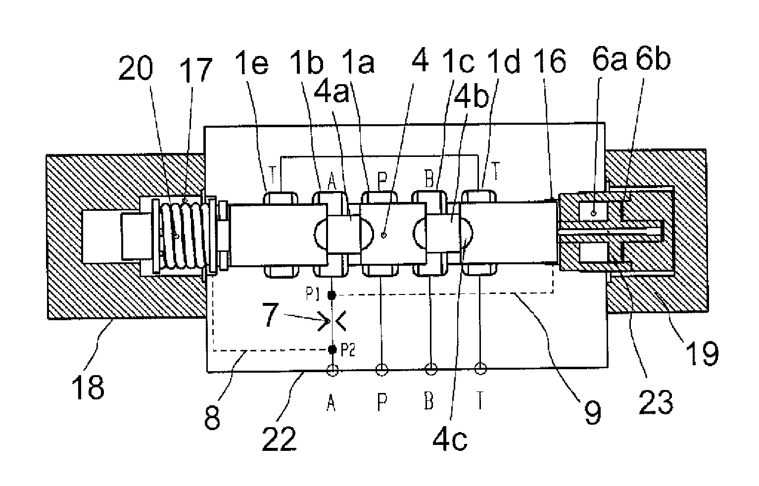
[0028]FIG. 1 shows, by means of graphic symbols of hydraulics and on the principle level, a directional valve in which the compensation according to the presented solution is applied. It is a valve that is particularly suitable for hydraulic oil or various flowing hydraulic fluids.

[0029]The valve 1 of FIG. 1 is a so-called 4 / 3 directional valve. The valve 1 comprises a spool 4 which is arranged, in the centre position of the valve 1, to close a pressure port P, a tank port T, and both work ports A and B. When the valve 1 is not under pilot control, the spool 4 is automatically set in the centre position, for example centered by means of springs 5a, 5b. The spool 4 is deviated from the centre position by applying forces generated by the pilot control. The spring force generated by the spring is used as a returning force and a counterforce for the force of the pilot control. Said force tends to move the spool to a desired position (e.g. the centre coupling position in FIG. 1), when th...


PUM


Abstract

A directional valve for controlling an actuator by means of pressurized medium, including: a spool fitted to move axially inside the directional valve; a first position of the spool, in which the spool tends to be set; and a second position of the spool, to which the spool can be moved by a pilot control force. Additionally, the directional valve includes a metering orifice placed in the pressure port or in the first work port or in the second work port or in the tank port, and across which a pressure difference is effective. The spool further includes a second position, to which the spool can be moved by a pilot control force. When the spool is in at least the second position, the directional valve is fitted to generate a compensating force proportional to said pressure difference, to move the spool to compensate for the flow.

Description

FIELD OF THE INVENTION[0001]The invention relates to a directional valve for controlling an actuator by means of pressurized medium.BACKGROUND OF THE INVENTION[0002]In pressurized medium systems, actuators which perform rotary or linear motions, such as motors and cylinders, are utilized in a known manner. In controlling the actuators, valves are utilized for controlling the pressurized medium for example to control the direction of movement of the actuator or to keep it stationary. Different functions of the actuators are implemented by suitable couplings of different valves.[0003]Several different couplings for controlling an actuator are implemented particularly in directional valves comprising a spool which is axially movable in a bore in the valve body and which, in its different positions, couples the different connections and ports of the valves in a desired way. The different channels of the valve are connected to the connections and ports. Typically, the different channels ...

Claims


Application Information

Patent Timeline
Patent Type & Authority Patents(United States)
IPC IPC(8): F15B11/08F16K11/07F15B13/16F15B13/04
CPCF15B11/08F15B13/0416F15B13/16F16K11/0716F15B13/0402F15B2211/30525F15B2211/329F15B2211/365Y10T137/87193F15B21/00
Inventor LIUKKUNEN, TOMMI
Owner PARKER HANNIFIN MFG FINLAND
Learn More