
System and method for controlling exhaust emissions and specific fuel consumption of an engine

a technology of specific fuel consumption and exhaust emissions, which is applied in the direction of electric control, machines/engines, mechanical equipment, etc., can solve the problems of affecting engine performance, efficiency, exhaust pollutants, other engine characteristics, and diesel engines operating in mountainous regions are subject to greater loads due to higher gradients and the air density is reduced

Active Publication Date: 2015-09-22
GE GLOBAL SOURCING LLC
View PDF28 Cites 5 Cited by
  • Summary
  • Abstract
  • Description
  • Claims
  • Application Information

AI Technical Summary

Problems solved by technology

These environmental conditions can adversely affect engine performance, efficiency, exhaust pollutants, and other engine characteristics.
For example, diesel engines operating in mountainous regions are subject to greater loads due to higher gradients, lower atmospheric pressures due to higher altitudes, lower temperatures due to colder climate or higher altitude, lower air density due to lower atmospheric pressure, and the like.
The various engine parameters are particularly susceptible to exceed engine design limits when the engine is operating at a full load at extreme ambient temperature and altitude conditions.
It is difficult to adequately account for the impact of ambient conditions to control exhaust emissions and specific fuel consumption of the engine to specific limits.

Method used


Image

  • System and method for controlling exhaust emissions and specific fuel consumption of an engine
  • System and method for controlling exhaust emissions and specific fuel consumption of an engine
  • System and method for controlling exhaust emissions and specific fuel consumption of an engine

Examples


Embodiment Construction

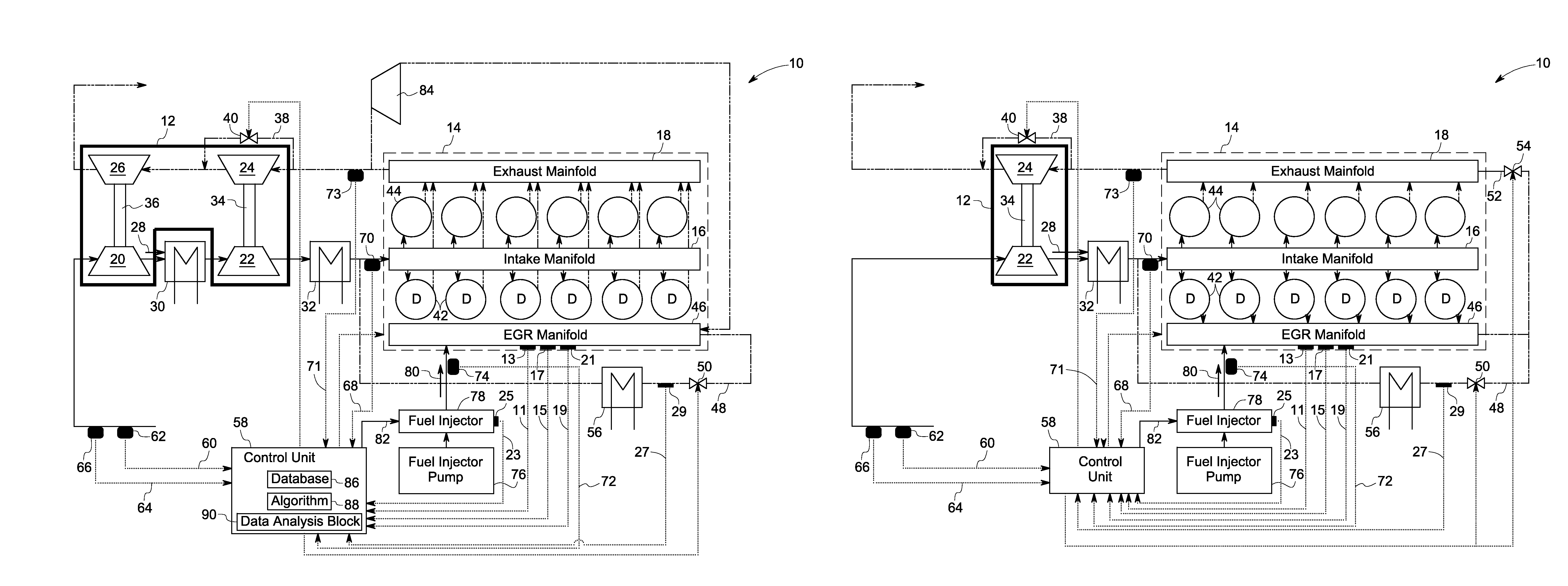
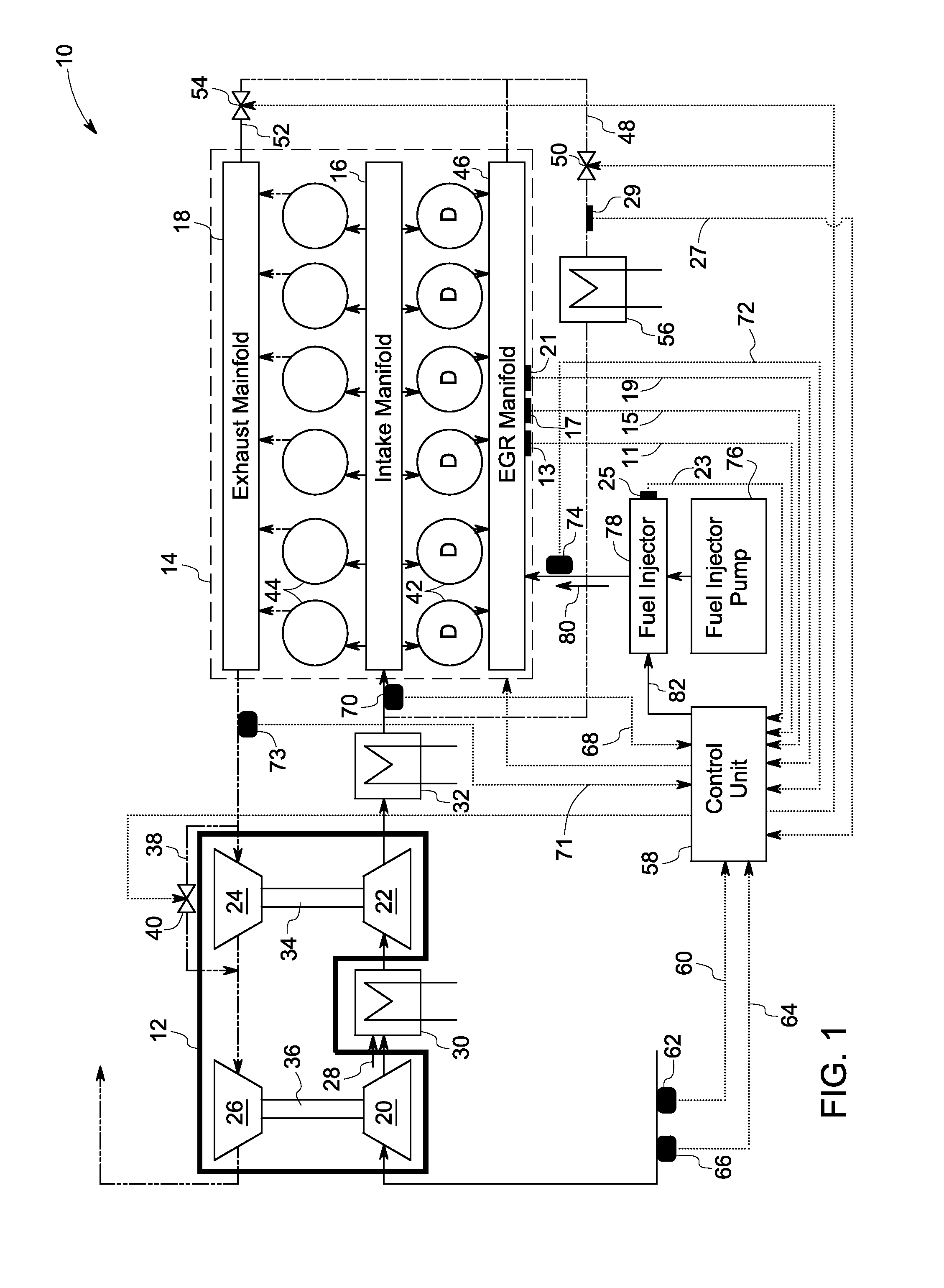
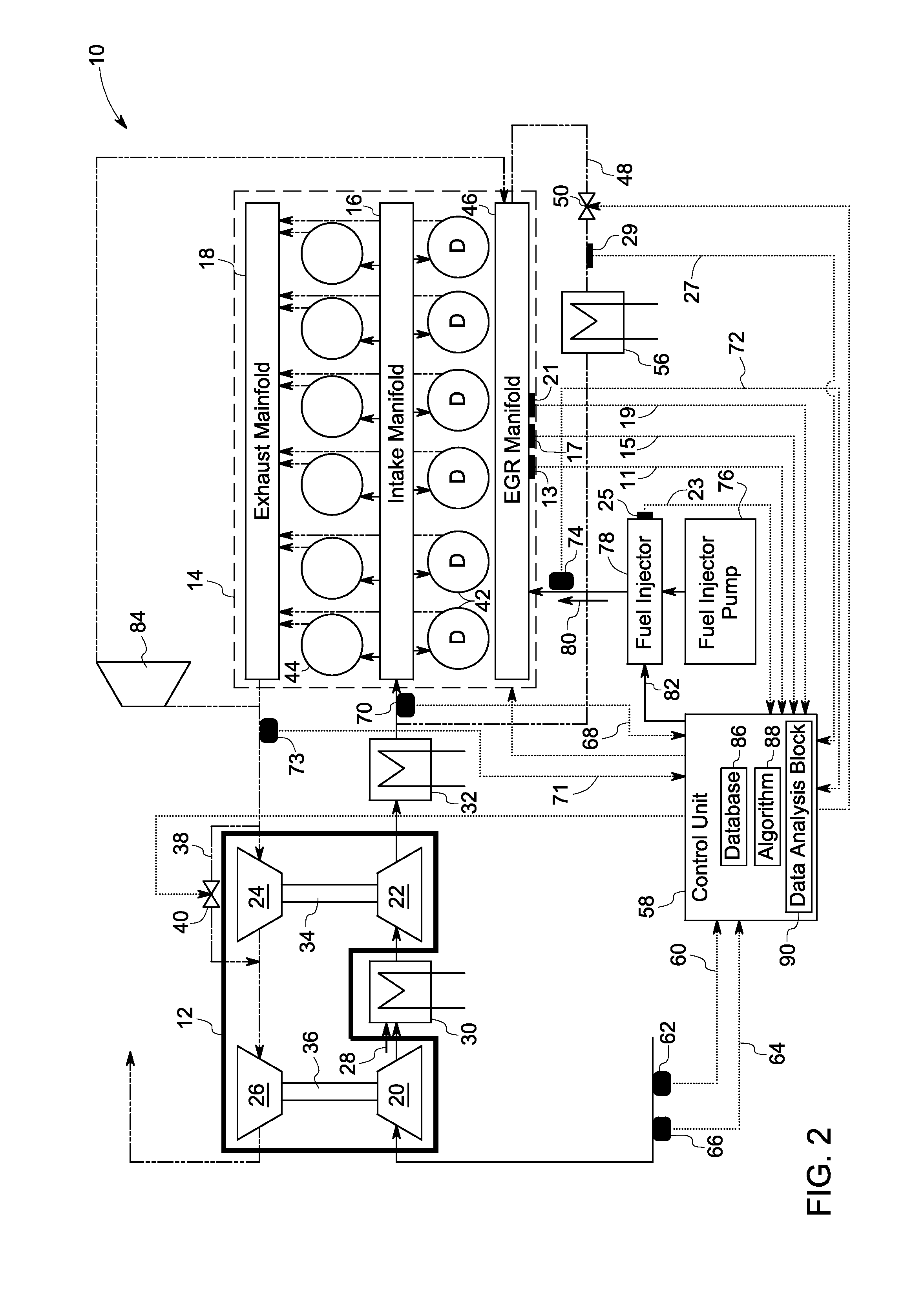
[0014]Referring to FIG. 1, a turbocharged unit 10 having exhaust emission and specific fuel consumption (SFC) control features, is illustrated in accordance with certain embodiments of the present invention. The turbocharged unit 10 includes a turbo-charger 12 and a compression-ignition engine, e.g., a diesel engine 14. A motor-generator unit (not shown) may be mechanically coupled to the turbocharger 12. As discussed in further detail below, embodiments of the present invention provide monitoring and control features, such as sensors and control logic, for maintaining a SFC of the engine 14 and a quantity of exhaust emissions in the exhaust gas, within a predefined SFC limit and an emission limit respectively, by controlling feed of a portion of the exhaust gas bypassing a turbine and / or recirculating a portion of the exhaust gas to the engine 14, as a function of ambient conditions such an intake manifold air temperature and pressure at which the engine 14 is operated. In certain ...


PUM


Abstract

A method includes combusting air within a plurality of cylinders of an internal combustion engine by injecting a fuel into the plurality of cylinders. The method further includes expanding a first portion of an exhaust gas generated from the plurality of combustion cylinders via a turbine. The method further includes controlling at least one of feeding a second portion of the exhaust gas via an exhaust channel bypassing the turbine; and recirculating a third portion of the exhaust gas to the plurality of combustion cylinders via a recirculation channel, as a function of an intake manifold air temperature and pressure at which the engine is operated.

Description

BACKGROUND[0001]The embodiments of the present invention relate generally to a system and method of operating an engine and, more specifically, to a system and method for controlling exhaust emissions and specific fuel consumption of an engine.[0002]Compression-ignition engines, such as diesel engines, operate by directly injecting a fuel (e.g., diesel fuel) into compressed air in one or more piston-cylinder assemblies, such that the heat of the compressed air ignites the fuel-air mixture. Compression-ignition engines may also include a glow plug to provide heat to ensure ignition. The direct fuel injection atomizes the fuel into droplets, which evaporate and mix with the compressed air in the combustion chambers of the piston-cylinder assemblies. Typically, compression-ignition engines operate at a relatively higher compression ratio than spark ignition engines. The compression ratio directly affects the engine performance, efficiency, exhaust pollutants, and other engine character...

Claims


Application Information

Patent Timeline
Patent Type & Authority Patents(United States)
IPC IPC(8): F02M25/07F02B37/00F02B37/18F02D41/00F02B37/013F02B29/04
CPCF02B37/004F02B37/013F02B37/18F02D41/0007F02D41/0052F02M25/0707F02M25/0711F02M25/0749F02B29/0412F02B29/0425F02B29/0437F02D2200/0414F02D2200/703F02M25/0713F02M25/0727F02M25/0739F02M25/0754Y02T10/144Y02T10/47F02M26/43F02M26/05F02M26/08F02M26/10F02M26/23F02M26/34F02M26/47Y02T10/12Y02T10/40
Inventor PRIMUS, ROY JAMESAKINYEMI, OMOWOLEOLA CHUKWUEMEKALAVERTU, THOMAS MICHAELMISCHLER, JAMES ROBERTGUMMADAVELLI, VENU GOPAL
Owner GE GLOBAL SOURCING LLC
Learn More