
Electrical energy regenerative system, network and method

a technology of electrical energy regenerative system and closed loop, applied in the field of closed loop electrical energy regenerative system and network and method, can solve problems such as inefficient energy us

Inactive Publication Date: 2015-09-15
SUSTAINABILITY RES & DEV L L C
View PDF4 Cites 3 Cited by
  • Summary
  • Abstract
  • Description
  • Claims
  • Application Information

AI Technical Summary

Benefits of technology

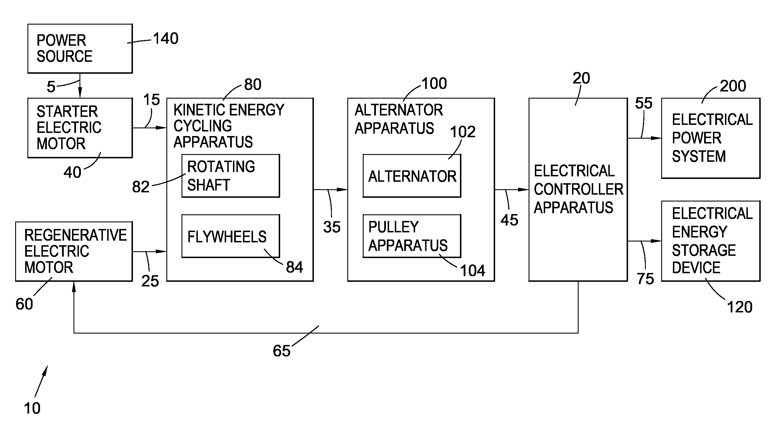
The present invention provides an electrical energy regenerative system, network, and method that eliminates the disadvantages of the prior art. It includes a rotating shaft and at least one flywheel to transfer kinetic energy from a regenerative electric motor to an alternator for generating electrical energy output and to the flywheel for storage to assist in rotating the shaft. The system also includes a pulley apparatus to increase the rotational speed of the alternator beyond the rotating shaft's speed. The technical effects include improved energy efficiency and recycling of energy, reduced energy waste, and improved performance of the system.

Problems solved by technology

This generally results in an inefficient use of energy when used in applications having a fluctuation need of energy through time.

Method used


Image

  • Electrical energy regenerative system, network and method
  • Electrical energy regenerative system, network and method
  • Electrical energy regenerative system, network and method

Examples


Embodiment Construction

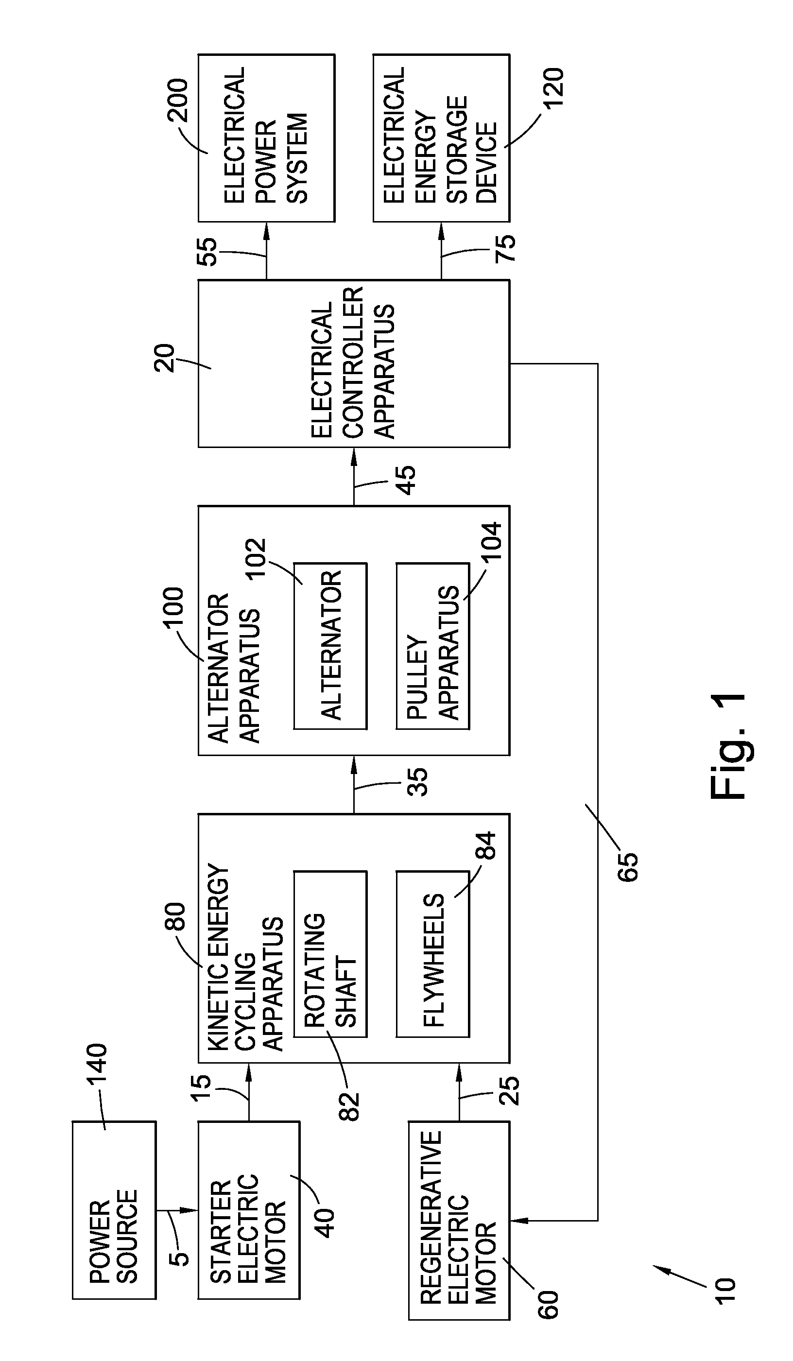
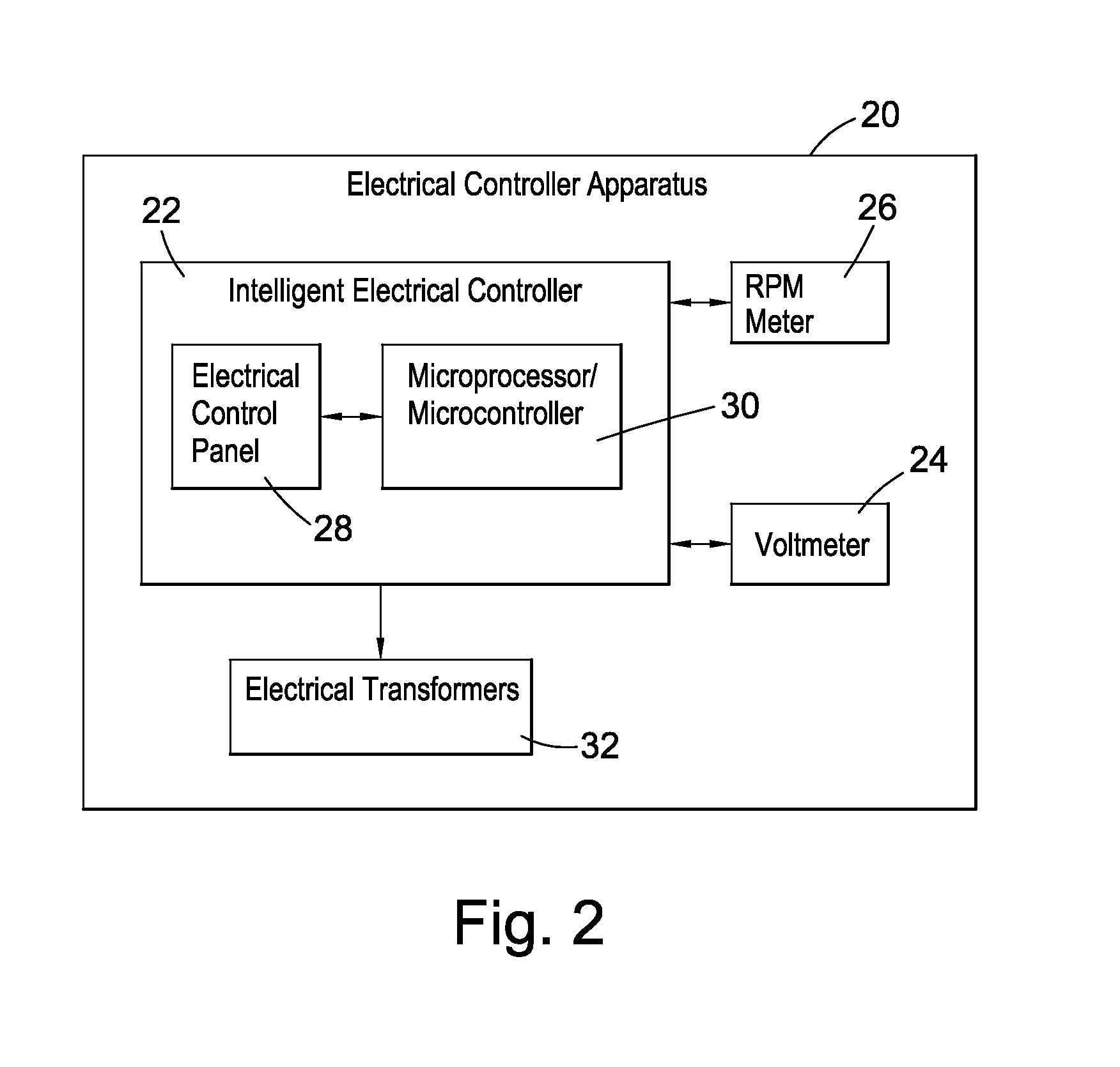
[0062]Referring to FIGS. 1 and 2, as a first aspect of the invention, there is provided an electrical energy regenerative system 10 comprising:[0063]An electrical controller apparatus 20;[0064]A starter electric motor 40;[0065]A regenerative electric motor 60;[0066]A kinetic energy cycling apparatus 80;[0067]An alternator apparatus 100; and[0068]An electrical energy storage device 120.

[0069]The electrical controller apparatus 20 is essentially the nervous system of the system 10 which coordinates its activities through the measurement, regulation, transformation and distribution of power obtained / distributed from / to the different components of the system 10 and / or external environment. The electrical controller apparatus 20 comprises an intelligent electrical controller 22 configured to be connected to the starter electric motor 40, to the regenerative electric motor 60, to the kinetic energy cycling apparatus 80, to the alternator apparatus 100 and to the electrical energy storage ...


PUM


Abstract

There is provided a closed-loop electrical energy regenerative system comprising (i) a regenerative electric motor for receiving a load of electrical energy for the purpose of conversion into kinetic energy; (ii) an alternator for generating an output load of electrical energy; (iii) a rotating shaft and at least one flywheel, the rotating shaft being configured to be connected to the regenerative electric motor, to the alternator and to the at least one flywheel for transferring a first portion of the kinetic energy from the regenerative electric motor to the alternator for the purpose of generating the output load of electrical energy and for transferring a second portion of the kinetic energy to the at least one flywheel for storage for the purpose of assisting in rotating the rotating shaft through subsequent cycles; (iv) a first electrical output for directing a first portion of the output load of electrical energy outside the system for consumption by an electric power system; and a second electrical output for directing a second portion of the output load of electrical energy back to the regenerative electric motor for operation through the subsequent cycles. There is also provided a closed-loop electrical energy regenerative network and method.

Description

FIELD OF THE INVENTION[0001]The present invention is generally related to electric generators and more particularly to a closed-loop electrical energy regenerative system, network and method.BACKGROUND OF THE INVENTION[0002]Electric motors are used in a wide range of industries for converting kinetic energy into electrical energy. Traditional electric generators convert all the kinetic energy received into electric energy for a subsequent use in various applications, regardless of the effective need of electrical energy of these applications and variation thereof through time. Traditional systems comprising electric motors are open loop systems using an input unit of energy to generate an output unit of energy. This generally results in an inefficient use of energy when used in applications having a fluctuation need of energy through time.SUMMARY OF THE INVENTION[0003]It is an object of the present invention to eliminate the disadvantages of the prior art by providing an electrical ...

Claims


Application Information

Patent Timeline
IPC IPC(8): H02P1/00H02K47/14
CPCH02K47/14H02K53/00Y10S74/09H02J7/0068H02K7/025H02P9/04
Inventor ALKHOORI, SAWSAN MOHAMMED SHUAIB
Owner SUSTAINABILITY RES & DEV L L C
Learn More