
Transport chain and transport chain system

a technology of transport chain and chain system, which is applied in the field of transport chain, can solve the problems of limiting the size of the sliding surface of the goods-carrying object, unable to achieve relative movement with respect to the ball, radial and axial movement, etc., and achieves the effect of not expensive or time-consuming to manufacture, mount or disassembl

Inactive Publication Date: 2015-09-08
CARRYLINE
View PDF13 Cites 3 Cited by
  • Summary
  • Abstract
  • Description
  • Claims
  • Application Information

AI Technical Summary

Benefits of technology

The invention provides a transport chain with a chain link and a substantially spherical bearing element. The chain link is made of a plurality of branches, and the bearing element is inserted into a cavity past the branches in a direction parallel to the transport direction of the chain. The plurality of pins is arranged to provide torsional rigidity for the chain link and the bearing element, and can be cylindrical or non-cylindrical. This design allows for a simple and cost-effective transport chain that can be easily mounted and disassembled without special tools.

Problems solved by technology

This construction has a complicated structure and because of its Cardan joint results in a wide construction and thereby limits the size of the goods-carrying sliding surface against a sliding list.
Another disadvantage is that the Cardan joint is not self-adjusting with respect to the main bearing that is constituted by the sliding surfaces between the goods-carrying plate's underside and the sliding list integrated into the conveyor beam.
The disadvantage of a centrally fixed pin in the ball is that the transmission of force from the ball to the following link is strongly concentrated at the nose section of the link and the ball, i.e. that part of the ball that lies at the front in the transport direction.
A further disadvantage is that large demands are placed on the pin being so fixedly anchored that relative movement with respect to the ball, both radial and axial, cannot occur.
This means that the pin requires both a large mounting force and also, during maintenance and repair work, a large disassembling force.
Often, the special tools that are required for such mounting and disassembling work are not available at client locations where the conveyors are installed.
Another disadvantage is that mounting and demounting of the ball is difficult so this is usually carried out from the side of the link and results in the formation of an opening that is larger than the diameter of the ball, which weakens the tensile strength of the construction.
The disadvantages of an integrated ball and pin are that such a component is expensive to manufacture, the wear between the steel ball and the following plastic link is relatively high and the force concentration from the ball to the following link is strongly concentrated at the nose sections of the link and the ball when the plastic chain is in use.
The plastic material around the pin can therefore become deformed during use, which can create undesired play between the transport chain's components, which can in turn decrease the lifetime of the plastic chain and create noise.

Method used


Image

  • Transport chain and transport chain system
  • Transport chain and transport chain system
  • Transport chain and transport chain system

Examples


Embodiment Construction

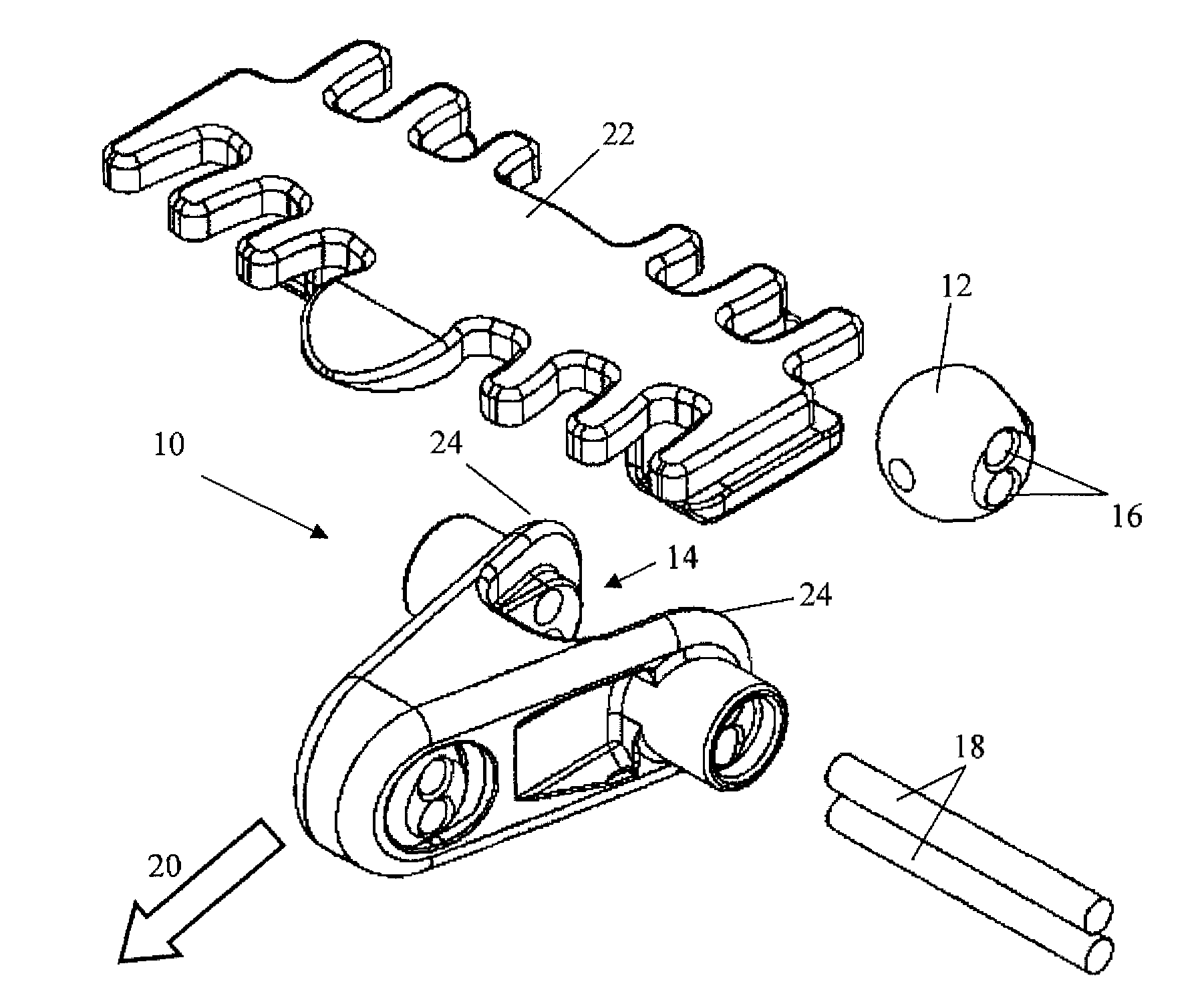
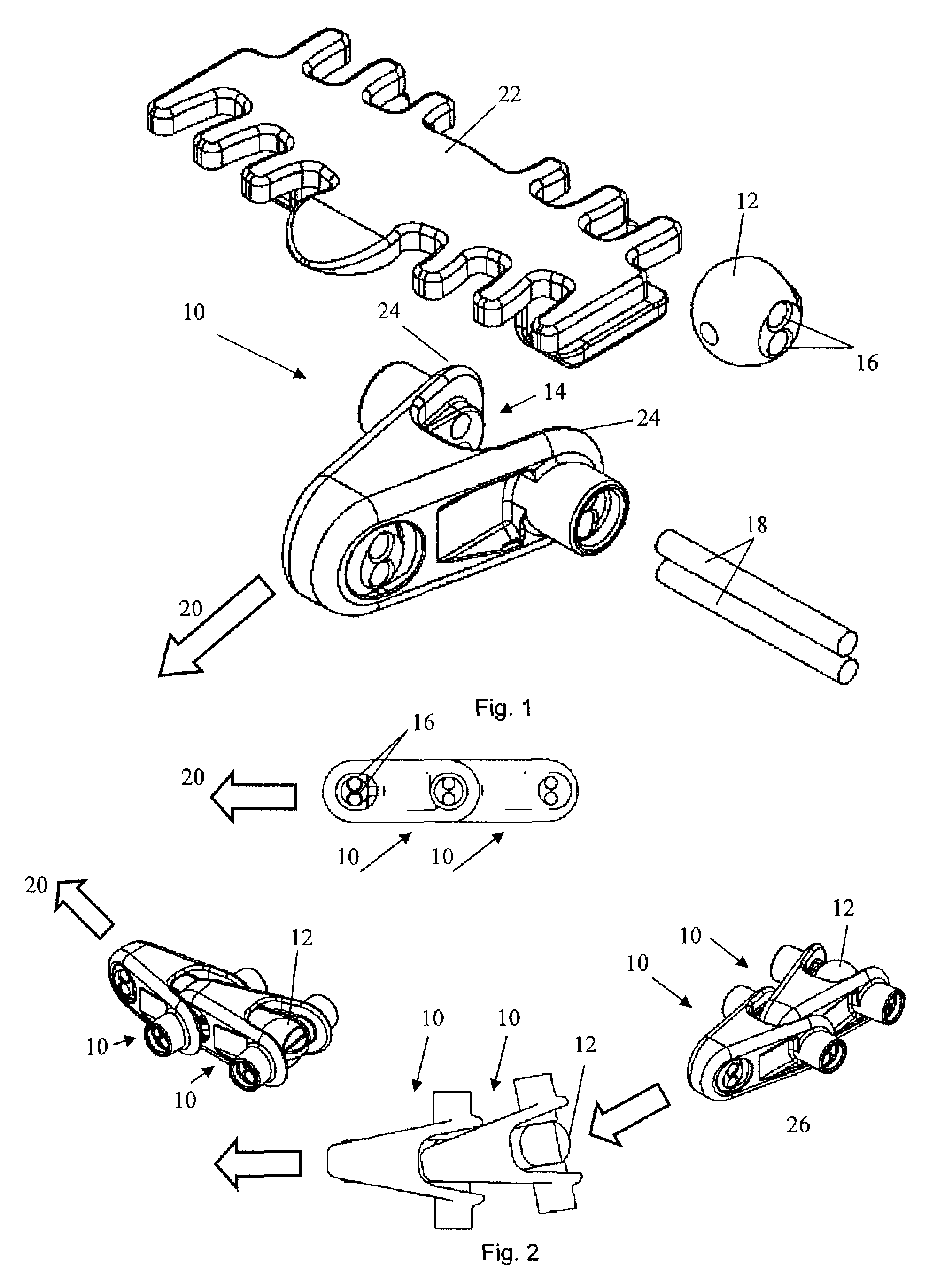
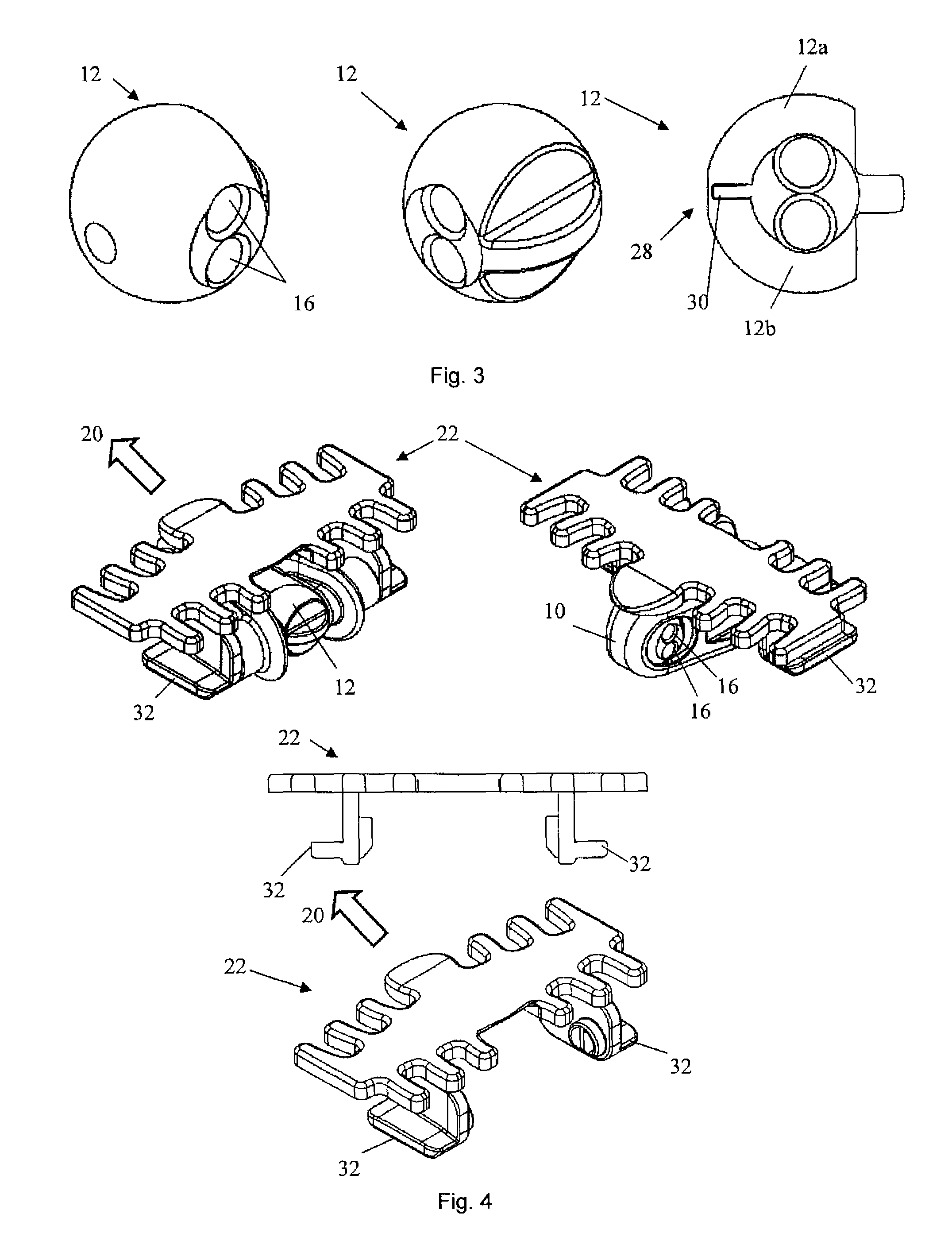
[0035]FIG. 1 shows a chain link 10 that is intended to be connected to a following similar or identical chain link by means of a joint segment that is placed between the chain link 10 and the following chain link. The joint segment comprises a bearing element 12 and the chain link 10 comprises a cavity 14 with a substantially spherical surface arranged to receive said bearing element 12. The bearing element 12 is substantially spherical and comprises a plurality of through holes 16. The cavity 14 can have a corresponding substantially spherical contact surface for receiving the bearing element 12. The joint segment also comprises a plurality of pins 18 that is arranged in said through holes 16 both in the joint segment and in the following link when the transport chain is in use. The pins 18 create torsional rigidity with respect to the substantially spherical bearing element 12 and the chain link 10 when the transport chain is in use.

[0036]The pins 18 can be symmetrically or asymme...


PUM


Abstract

Transport chain for transporting objects along a transport path in a transport direction, which transport chain comprises a plurality chain links that is interconnected using a joint segment between each chain link, which joint segment comprises a bearing element. Each chain link in the part that is located at the back in the transport direction comprises a cavity that is arranged to receive the bearing element. The bearing element is substantially spherical and comprises a plurality of through holes. The joint segment also comprises a plurality of pins that is arranged in the through holes in the bearing element and in openings in the chain link and in openings in the following chain link.

Description

PRIORITY INFORMATION[0001]This application claims priority to SE Application No. SE1350634-0 filed on May 24, 2013, the contents of which are incorporated herein by reference in its entirety.TECHNICAL FIELD[0002]The present invention concerns a transport chain for transporting objects along a transport path in a direction of travel, which transport chain comprises a plurality of interconnected chain links. The present invention also concerns a transport chain system comprising a transport path and such a transport chain.BACKGROUND OF THE INVENTION[0003]Transport chains are used in industry to move objects from one place to another, for example in a factory. A transport chain can be constructed from a plurality of links that are similar in appearance and function and that are connected with one another. The connections between the links make it possible for the links to pivot relative to one another around two perpendicular axes of rotation which each extend with respect to the trans...

Claims


Application Information

Patent Timeline
Patent Type & Authority Patents(United States)
IPC IPC(8): B65G17/06B65G17/44B65G15/48
CPCB65G15/48B65G17/066B65G17/44B65G2207/12B65G17/086B65G17/385F16G13/10
Inventor HENREKSON, DAG
Owner CARRYLINE
Learn More