
Endoscope with preloaded or preloadable stent

a preloaded or preloaded stent technology, applied in the field of endoscope delivery systems and methods, can solve the problems of limiting the diameter of the contracted or loaded stent to a diameter larger than that of the endoscope, and the overall profile of the endoscope is limited to a relatively large siz

Active Publication Date: 2015-09-08
BOSTON SCI SCIMED INC
View PDF34 Cites 5 Cited by
  • Summary
  • Abstract
  • Description
  • Claims
  • Application Information

AI Technical Summary

Benefits of technology

This solution enables precise and efficient delivery of stents across different bodily lumens, overcoming size constraints and design limitations, facilitating accurate stent placement and deployment while accommodating various stent configurations.

Problems solved by technology

Such a procedure has size limitation, especially for smaller bodily lumens, as both the endoscope and the stent delivery catheter must be navigated to the damaged vessel.
The combining of a stent delivery catheter and an endoscope in such a manner, however, limits the diameter of the contracted or loaded stent to a diameter larger than that of the endoscope.
pe. Again, the overall profile of the endoscope is limited to a relatively large size as the endoscope must be sized for accenting the stent delivery cathe
Such a system makes stent placement difficult as the stent is pushed away from the distal end of the endoscope.
Further, the need of rings or tubes at the ends of the stent which are smaller in diameter than the diameter of the expanded stent, limits the use of such a stent as the smaller ends of the stent will tend to restrict flow through the stent.
Again the pushing of the stent out of the endoscope is problematic as accurate stent placement is difficult.
Further, the device of Seldon is apparently limited to a particular stent design, i.e., a highly flared configuration with only the very terminal end portions of the stent being engageable with the wall to the endoscope such that the longitudinal expanse of the stent does not engage the wall of the endoscope as the stent is being pushed out of the endoscope.

Method used


Image

  • Endoscope with preloaded or preloadable stent
  • Endoscope with preloaded or preloadable stent
  • Endoscope with preloaded or preloadable stent

Examples


Embodiment Construction

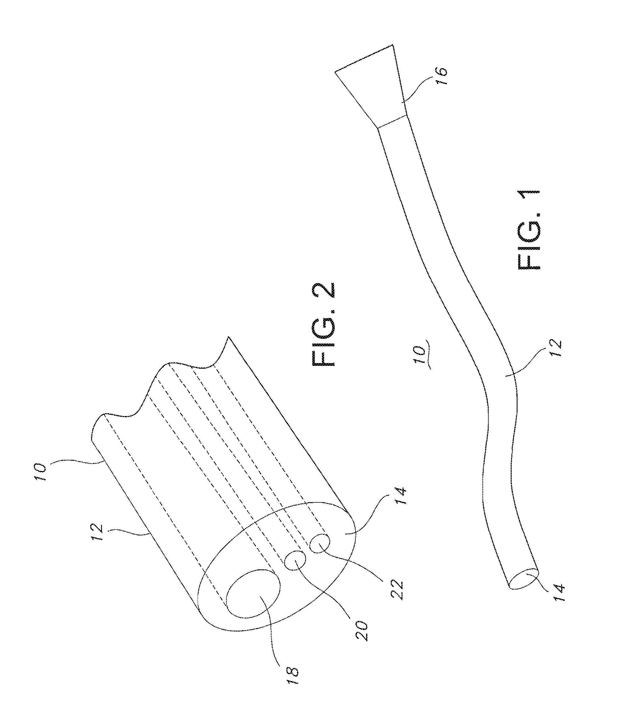
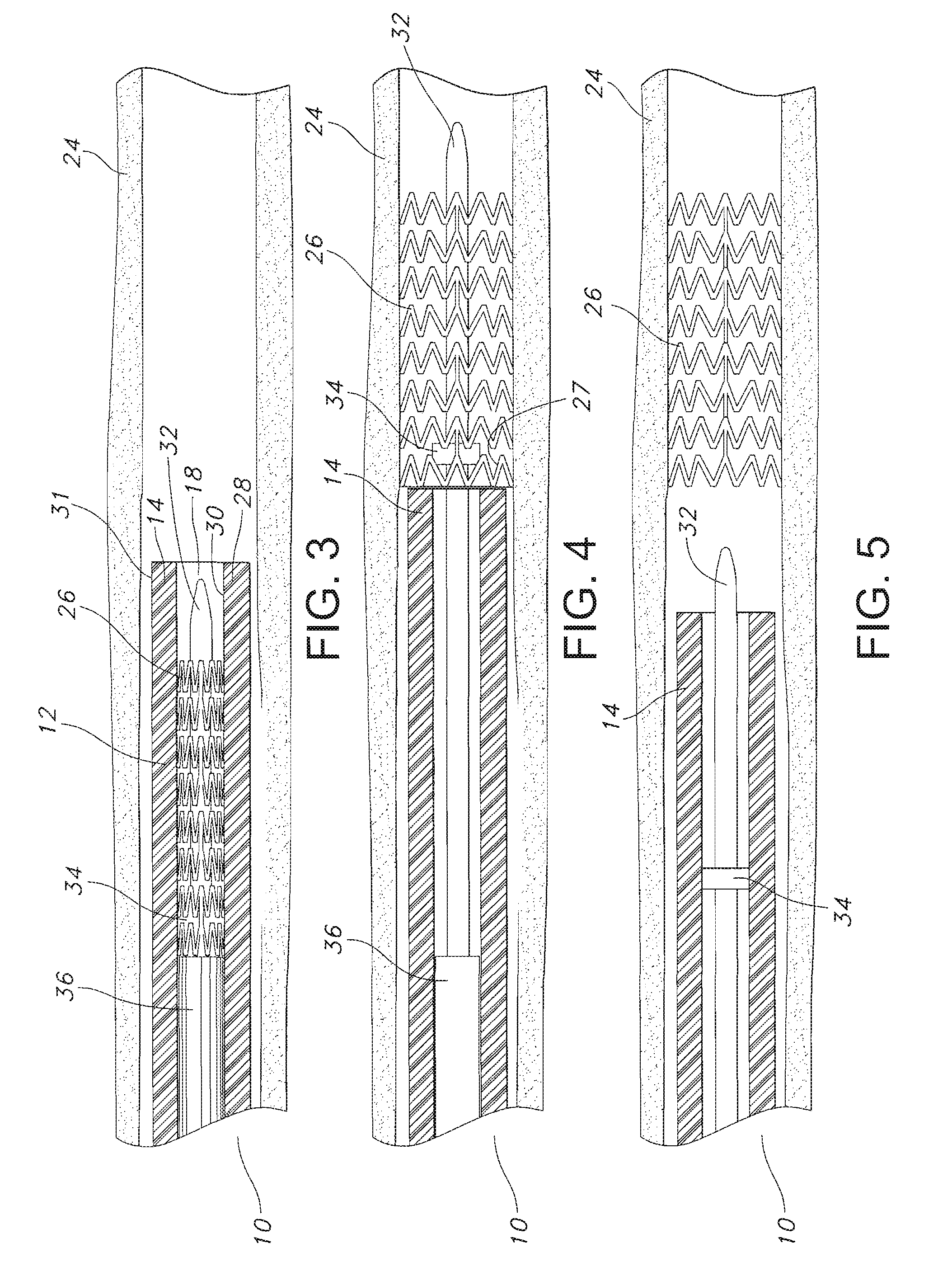
[0030]The present invention relates to an endoscopic assembly and method for transporting and deploying a stent or other intraluminary member, as described herein, in a bodily passageway. The assembly is useful for medical applications in, but not limited to, the gastrointestinal tract, the biliary, tract, the urinary tract, and the respiratory tract. In particular, a preferred embodiment of the present invention is directed to an endoscopic delivery system having a stent loaded into a working channel. The stent may be loaded into the working channel of the endoscope either by a manufacturer of the assembly or by a practitioner of the assembly prior to use. The endoscope may be a disposable endoscope or a non-disposable endoscope. The endoscopic assembly and method of the present invention is particularly suitable for delivering a self-expanding esophageal stent. The endoscopic assembly in accordance with the present invention, however, could also be used in the neurological system ...


PUM


Abstract

The present invention is directed to an endoscopic stent delivery device. The device includes an endoscope having an elongate shaft including a proximal end, a distal end, an outer wall and a longitudinal working channel through the elongate shaft defining an inner wall of the elongate shaft; a stent juxtaposingly disposed to a distal portion of the inner wall; and an inner tubular member slidably disposed within the working channel and having a stent holding member engaging an interior portion of the stent for releasably securing the stent to the distal portion of the inner wall. The device may further include a viewing device disposed at the distal end of the endoscope and / or an illuminating device disposed at the distal end of the endoscope.

Description

CROSS-REFERENCE TO RELATED APPLICATIONS[0001]This application claims the benefit of U.S. Provisional Application No. 60 / 897,382, filed Jan. 25, 2007, the content of which is incorporated herein by reference.FIELD OF THE INVENTION[0002]This invention relates to a system and method for endoscopic deliver of a stent. More particularly, this invention relates to an endoscope having a preloaded or preloadable stent, including a radially distensible, polymeric and / or non-polymeric stent.BACKGROUND OF THE INVENTION[0003]An intraluminary stent is a medical device used in the treatment of diseased bodily lumens, such as in the coronary or peripheral vasculature, esophagus, trachea, bronchi colon, biliary tract, urinary tract, prostate, brain, as well as in a variety of other applications in the body. Contemporary endoscopy practitioners increasingly often require visualization of the damaged vessel while delivering the stent. In some cases an endoscope and a stent delivery catheter are separ...

Claims


Application Information

Patent Timeline
Patent Type & Authority Patents(United States)
IPC IPC(8): A61F2/95A61F2/966
CPCA61F2/95A61F2/966A61F2002/9511A61F2002/9522A61B90/30A61B90/361A61F2/9522A61F2/07A61F2/844A61F2/915A61F2002/072A61F2002/91533
Inventor WOOD, MARK D.HEADLEY, JR., F. ANTHONYLEANNA, GARY J.
Owner BOSTON SCI SCIMED INC
Learn More