Object detection method with a rising classifier effect and object detection device with the same

a classifier and object detection technology, applied in the field of object detection methods, can solve the problems of increasing false recognition rate and search time, unable to integrate dynamic object detection and recognition methods with existing embedded systems, and difficult to piece together the complete obstacle contour, etc., to achieve the effect of enhancing the recognition accuracy of a classifier, rapid calculation of desired numerical values, and fast computing speed

Active Publication Date: 2015-09-01
AUTOMOTIVE RES & TESTING CENT
View PDF6 Cites 0 Cited by
  • Summary
  • Abstract
  • Description
  • Claims
  • Application Information

AI Technical Summary

Benefits of technology

[0008]An objective of the present invention is to provide an object detection method with a rising classifier effect and an object detection device with a rising classifier effect being advantageous in complete extraction, higher recognition rate, faster computation and feasibility to be integrated with vehicle systems.
[0018]The algorithm for Poisson gradient vector flow based active deformable contour model is used to convert image information into a flow field distribution. The calculus of variations is used to extract a contour of the obstacle. The multi-mesh algorithm is used to rapidly calculate out desired numerical values and achieve faster computing speed. When the object detection device is mounted in a vehicle, a road detection range can be configured according to a corresponding field of view to the vehicle. The object detection device does not require any additional sensor to perform conditional determination based on a specific road safety scenario and to provide dynamic object detection and recognition and an alerting function. Accordingly, the present invention enhances the recognition accuracy of a classifier, and resolves the issues of conventional dynamic object detection and image recognition methods having an increased false recognition rate, being time consuming in computation and failing to be integrated with existing vehicle systems.

Problems solved by technology

In other words, when the extracted portions are too small, a complete obstacle contour is difficult to be pieced together because of discontinuous regions easily generated from each extracted portion.
The consequence is an increased false recognition rate and lengthy search time.
If requiring calculation of image characteristic values of an image on each divided portion of the obstacle and a logical mechanism to determine types of objects of the images on the divided portions, the foregoing dynamic object detection and recognition methods are not easy to be integrated with existing embedded systems, and also have the issue of long processing time.
When the foregoing object detection and recognition methods are applied to recognize obstacles in the proximity of a vehicle in various occasions, such as while driving backwards or alerting for front-end collision, the methods are not appropriate for vehicular applications due to the drawbacks of being tune-consuming in image processing, high false recognition rate, and integration difficulties with existing vehicle systems.
Moreover, conventional obstacle-locating techniques for vehicular applications equip vehicles with millimeter wave radar, which is advantageous in long measuring distance, stable operation, weatherproof capability, and capability of measuring distance and relative speed between vehicles, but disadvantageous in high equipment cost and operation cost.
Such strategy has the advantage of requiring no other assistance equipment, but the disadvantage thereof is huge amount of calculation and long processing time.

Method used


Image

  • Object detection method with a rising classifier effect and object detection device with the same
  • Object detection method with a rising classifier effect and object detection device with the same
  • Object detection method with a rising classifier effect and object detection device with the same

Examples


Embodiment Construction

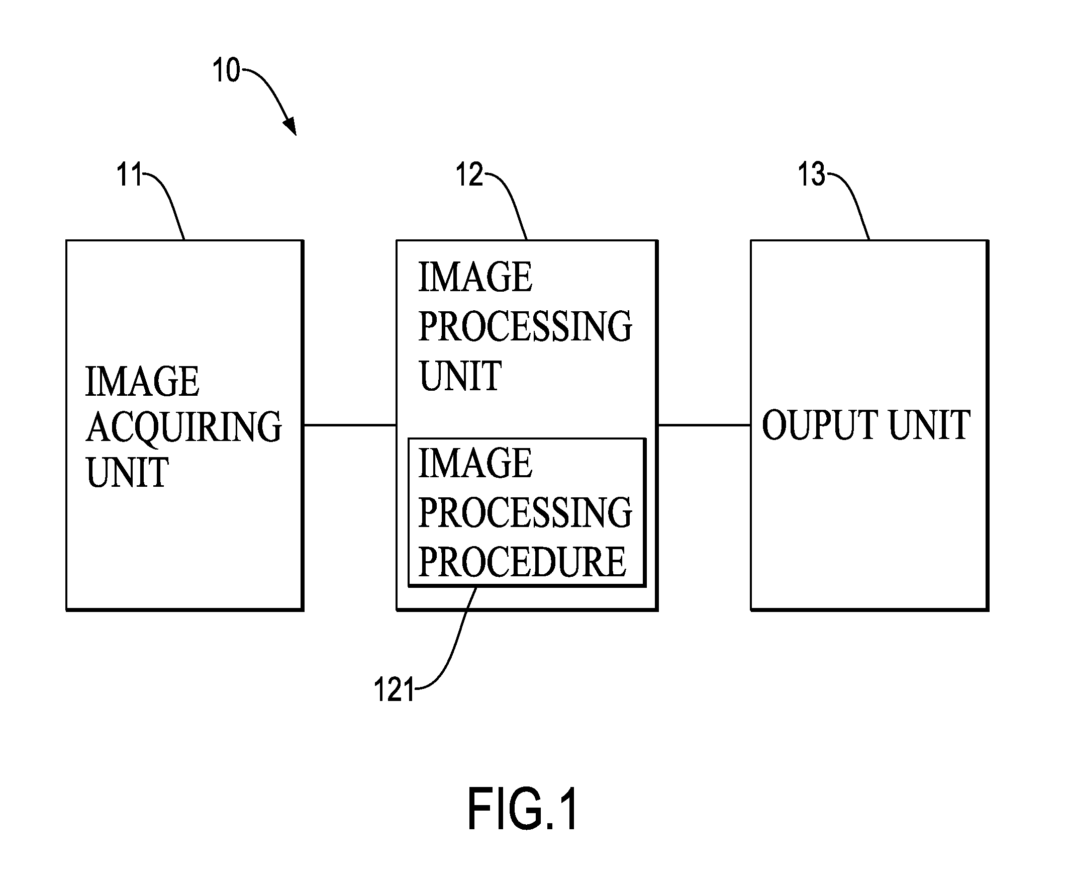
[0026]With reference to FIG. 1, an object detection device 10 with a rising classifier effect in accordance with the present invention is embedded in a vehicle and has an image acquiring unit 11, an image processing unit 12 and an output unit 13 sequentially connected to one another.

[0027]The image acquiring unit 11 acquires at least one image. The image processing unit 12 recognizes a contour of an obstacle in each of the at least one image and a type of the obstacle. The output unit 13 issues an alert. Accordingly, the object detection device 10 achieves the goal of recognizing an obstacle in the vicinity of a vehicle.

[0028]The image acquiring unit 11 includes at least one CCD (Charge-Coupled Device) camera or at least one CMOS (Complementary Metal Oxide Semiconductor) camera mounted on a front end, a rear end, a left side or a right side of the vehicle to take at least one image around the vehicle or includes multiple CCD cameras or CMOS cameras to take a panoramic image around t...


PUM


Abstract

An object detection method with a rising classifier effect is embedded in an object detection device and has steps of acquiring image information; determining a position of an obstacle in the image information, wherein the image information is detected for generation of an extracted range corresponding to the obstacle; recognizing an extracted contour of the obstacle, wherein the extracted contour of the obstacle associated with the extracted range is obtained by using an algorithm for Poisson gradient vector flow based active deformable contour model and a multi-mesh algorithm with different grid sizes; and forming a maximum border of the extracted contour of the obstacle for a classifier to recognize a type of the obstacle according to the maximum border of the obstacle. Accordingly, the object detection method is advantageous in complete extraction, higher recognition rate, faster computation and feasibility to be integrated with vehicle systems.

Description

BACKGROUND OF THE INVENTION[0001]1. Field of the Invention[0002]The present invention relates to an object detection method, and more particularly to an object detection method with a rising classifier effect.[0003]2. Description of the Related Art[0004]Recent dynamic object detection and recognition methods for recognizing various image formats can only extract certain portions of an obstacle in an image, and after dividing the extracted portions, can then determine to which type of object the Obstacle pertains by using an image comparison method to compare with other multiple known images. Hence, precision of the comparison and determination depends on integrity of the divided portions. In other words, when the extracted portions are too small, a complete obstacle contour is difficult to be pieced together because of discontinuous regions easily generated from each extracted portion. The consequence is an increased false recognition rate and lengthy search time.[0005]If requiring ...

Claims


Application Information

Patent Timeline
Patent Type & Authority Patents(United States)
IPC IPC(8): G06K9/00G06K9/62G06K9/46
CPCG06K9/00805G06K9/4604G06K9/6267G06K9/00832G06V20/58G06V10/755G06V20/59G06F18/24
Inventor YANG, CHIH-HUNGCHANG, KUO-CHING
Owner AUTOMOTIVE RES & TESTING CENT
Why Eureka
Try Eureka