
Object evaluation accounting for motion-related dynamic forces

a dynamic force and object evaluation technology, applied in the field of weighing vehicles in motion, can solve the problems of -time applications, dramatic change of attributes, and inability to accurately determine and utilize knowledge ahead of tim

Active Publication Date: 2015-09-01
INT ELECTRONICS MACHINES
View PDF38 Cites 31 Cited by
  • Summary
  • Abstract
  • Description
  • Claims
  • Application Information

AI Technical Summary

Benefits of technology

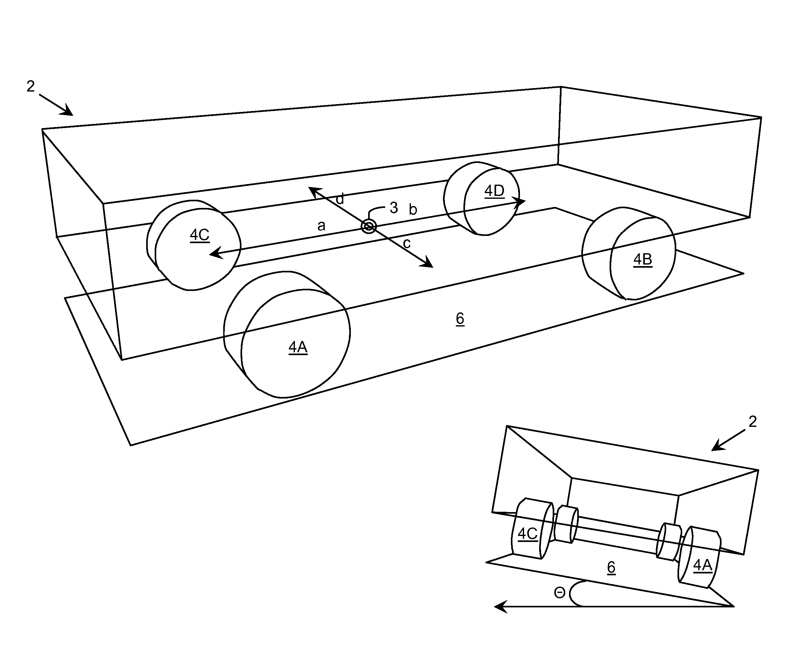
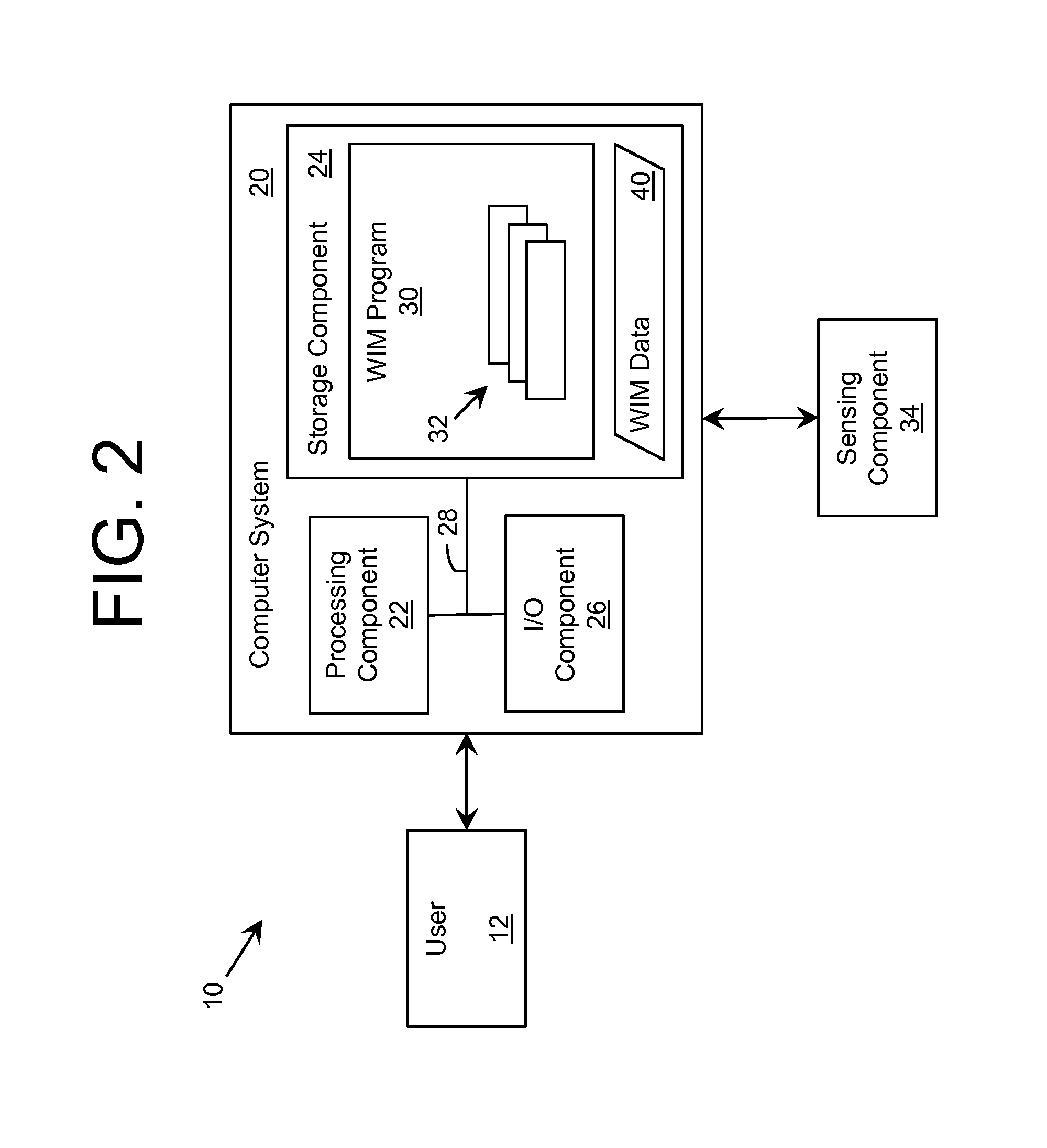
The invention provides a solution for evaluating objects, such as vehicles, by measuring the forces applied to a load plate as it moves through a sensing element. The sensing element includes vertical force sensing devices and horizontal force sensing devices located under the load plate. Measurements from these devices are used to calculate the weights of the object based on the static forces applied in the horizontal and vertical directions. This evaluation system can be used to weigh vehicles in motion as they travel over the load plates, providing accurate measurements even during movement.

Problems solved by technology

In practice, such knowledge cannot be accurately determined and utilized ahead of time, particularly in real-time applications.
More importantly, adding a significant load to a vehicle can result in an often dramatic change to the attributes.
Even with such restrictions, the accuracy of current WIM systems fail to meet reasonable requirements in many operating conditions.

Method used


Image

  • Object evaluation accounting for motion-related dynamic forces
  • Object evaluation accounting for motion-related dynamic forces
  • Object evaluation accounting for motion-related dynamic forces

Examples


Embodiment Construction

[0023]As indicated above, aspects of the invention provide a solution for evaluating an object, which accounts for various motion-related dynamic forces. In an embodiment, the object is a vehicle and the evaluation includes determining a set of static weights corresponding to the vehicle as it moves through a sensing element. The sensing element can include a load plate with vertical force sensing devices and horizontal force sensing devices located below the load plate. Analysis of measurement data acquired by the force sensing devices can enable calculation of the set of static weights corresponding to the vehicle. As used herein, unless otherwise noted, the term “set” means one or more (i.e., at least one) and the phrase “any solution” means any now known or later developed solution.

[0024]As described herein, to date, weigh-in-motion (WIM) approaches are limited in the type of vehicle and / or movements of a vehicle that are allowed during the weighing process in order to provide f...


PUM


Abstract

A solution for evaluating an object, which accounts for various motion-related dynamic forces is provided. In an embodiment, the object is a vehicle and the evaluation includes determining a set of static weights corresponding to the vehicle as it moves through a sensing element. The sensing element can include a load plate with vertical force sensing devices and horizontal force sensing devices located below the load plate. Analysis of measurement data acquired by the force sensing devices can enable calculation of the set of static weights corresponding to the vehicle.

Description

REFERENCE TO RELATED APPLICATIONS[0001]The current application claims the benefit of U.S. Provisional Application No. 61 / 573,178, titled “Accurate Weigh-in-Motion Device, System and Method,” which was filed on 19 Sep. 2011, and which is hereby incorporated by reference.GOVERNMENT LICENSE RIGHTS[0002]This invention was made with Federal government support under SBIR Contract No. W913E5-10-C-0004 awarded by the Department of Defense. The government has certain rights in the invention.TECHNICAL FIELD[0003]The disclosure relates generally to weighing vehicles in motion, and more particularly, to an improved solution for accurately weighing a vehicle while it is in motion.BACKGROUND ART[0004]To date, weigh-in-motion (WIM) approaches attempt to weigh a vehicle while it is in motion by considering the vertical forces generated by the vehicle. In order for such approaches to be reliable, various attributes of the vehicle design need to be known ahead of time, such as the precise loading of ...

Claims


Application Information

Patent Timeline
Patent Type & Authority Patents(United States)
IPC IPC(8): G01G19/02G01G19/04G01G23/00G01G19/03
CPCG01G19/035G01G19/047G01G23/002G01G19/024
Inventor MIAN, ZAHID F.GAMACHE, RONALD W.LIEBFRIED, CARL W.
Owner INT ELECTRONICS MACHINES
Learn More