Strain-control type tension-shearing direct shear apparatus
A technology of strain control and direct shear instrument, which is applied in the direction of testing material strength by applying stable shear force and testing material strength by applying stable tension/compression, which can solve the problem of not reflecting the strength characteristics of soil well and not having Directly measure the shear displacement device, increase the workload of experimenters and other problems, and achieve the effect of simple structure, reliable data and convenient operation
- Summary
- Abstract
- Description
- Claims
- Application Information
AI Technical Summary
Problems solved by technology
Method used
Image
Examples
Embodiment 1
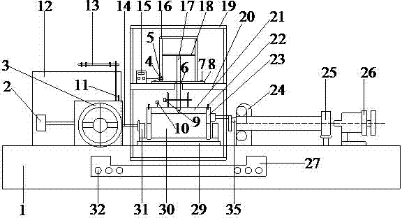
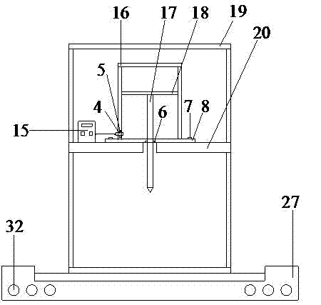
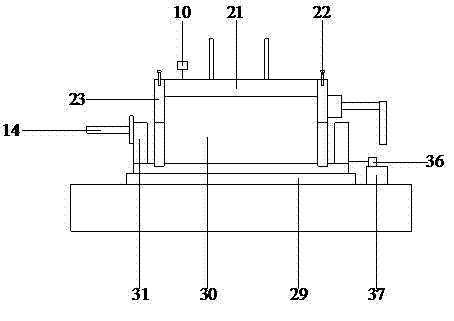
[0034] In order to measure the shear strength of the soil in the tension-shear region and realize the direct shear test in which the axial load is the tensile force, this embodiment provides a method such as figure 1 , figure 2 , image 3 and Figure 4 The strain-controlled tension-shear direct shear instrument includes a base 1 and a bracket 19 fixed on the base 1, and the base 1 is fixedly installed with a push seat 2, a sliding frame 29, and a measuring ring bearing in sequence from left to right. 24. Measuring ring part 25 and lock nut 26; a gearbox 12 is fixedly installed on the support on one side of the push seat 2, and a handwheel 3 is installed on one side of the push seat 2, and the push seat 2 and the gearbox Between 12, a bolt frame 13 is fixedly installed, and a bolt 11 is installed on the upper end of the push seat 2, and a lower shear box 31 is installed at the axial center of the upper surface of the sliding frame two 29, and the front end of the push seat 2...
Embodiment 2
[0039] On the basis of Example 1, such as Figure 5 As shown, the base 1 is fixedly equipped with a sliding frame one 27 by fixing bolts 32, the bracket 19 is installed in the sliding frame one 27, and the sliding frame one 27 is embedded with a roller shaft composed of a row of balls 28, and the sliding frame one 27 Not only as a working platform for the axial loading device, but also provide rollers to reduce the friction between the support 19 and the sliding frame 1 27, so that the axial loading device moves with the horizontal movement of the sample 30 during the shearing process, Avoid eccentric axial loading during testing.
[0040] Such as Figure 6 As shown, the connecting seat 21 is made of plexiglass, and there is a triangular groove in the center of its upper surface, and there are two protrusions with screw holes on both sides of the groove, and a plurality of drainage holes 33 are arranged inside the connecting seat 21 , for drainage during shearing.
[0041] ...
PUM
 Abstract
Description
Claims
Application Information
 - R&D
- Intellectual Property
- Life Sciences
- Materials
- Tech Scout
- Unparalleled Data Quality
- Higher Quality Content
- 60% Fewer Hallucinations
Browse by: Latest US Patents, China's latest patents, Technical Efficacy Thesaurus, Application Domain, Technology Topic, Popular Technical Reports.
© 2025 PatSnap. All rights reserved.Legal|Privacy policy|Modern Slavery Act Transparency Statement|Sitemap|About US| Contact US: help@patsnap.com


