Deposition apparatus

a technology of deposition apparatus and substrate, which is applied in the direction of chemical vapor deposition coating, vacuum evaporation coating, coating, etc., can solve the problems of accurate loading and unloading, damage to substrate supporting pins, so as to prevent damage to substrates and avoid the effect of reducing yield

Active Publication Date: 2015-09-01
ASM IP HLDG BV
View PDF4 Cites 0 Cited by
  • Summary
  • Abstract
  • Description
  • Claims
  • Application Information

AI Technical Summary

Benefits of technology

[0010]The present invention has been made in an effort to provide a deposition apparatus that can reduce or avoid damage of a substrate supporting pin and prevent the substrate supporting pin or a substrate from being damaged by preventing friction force which may be generated in a hole into which the substrate supporting pin is inserted by allowing the substrate supporting pin to move to a desired position, at the time of loading and / or unloading the substrate by using the substrate supporting pin.
[0019]According to the exemplary embodiment of the present invention, in a deposition apparatus, an autoalignment control unit is formed on a supporting pin supporter to which a fixed substrate supporting pin is fixed and the autoalignment control unit includes a direction control unit, such as a weight and an alignment guide ring, to automatically align a hole inserted with the supporting pin and a vertical movement axis of the substrate supporting pin, thereby preventing the substrate supporting pin from being broken or damaged due to internal friction with the hole. As a result, it is possible to prevent damaging the substrate, avoiding decrease in yield due to the breakage of the substrate supporting pin.

Problems solved by technology

In the case of the fixed supporting pin, the substrate supporting pin may be damaged due to friction with a lift pin hole formed on a susceptor or a heater.
As a result, the substrate supporting pin may be damaged.
As such, when the supporting pin is damaged or a vertical axis on which the substrate supporting pin moves is deformed, the substrate may not be loaded and unloaded accurately, and thus, the substrate may be even damaged.
Further, when the substrate is not loaded at an accurate position, process gas penetrates a rear surface of the substrate, and as a result, an unnecessary thin-film may be deposited or contaminated particles may be generated in a reactor.

Method used


Image

  • Deposition apparatus
  • Deposition apparatus
  • Deposition apparatus

Examples


Embodiment Construction

[0026]The present invention will be described more fully hereinafter with reference to the accompanying drawings, in which exemplary embodiments of the invention are shown. As those skilled in the art would realize, the described embodiments may be modified in various different ways, all without departing from the spirit or scope of the present invention.

[0027]In the drawings, the thickness of layers, films, panels, regions, etc., may have been exaggerated for clarity. Like reference numerals designate like elements throughout the specification. It will be understood that when an element such as a layer, film, region, or substrate is referred to as being “on” another element, it can be directly on the other element or intervening elements may also be present. In contrast, when an element is referred to as being “directly on” another element, there are no intervening elements present.

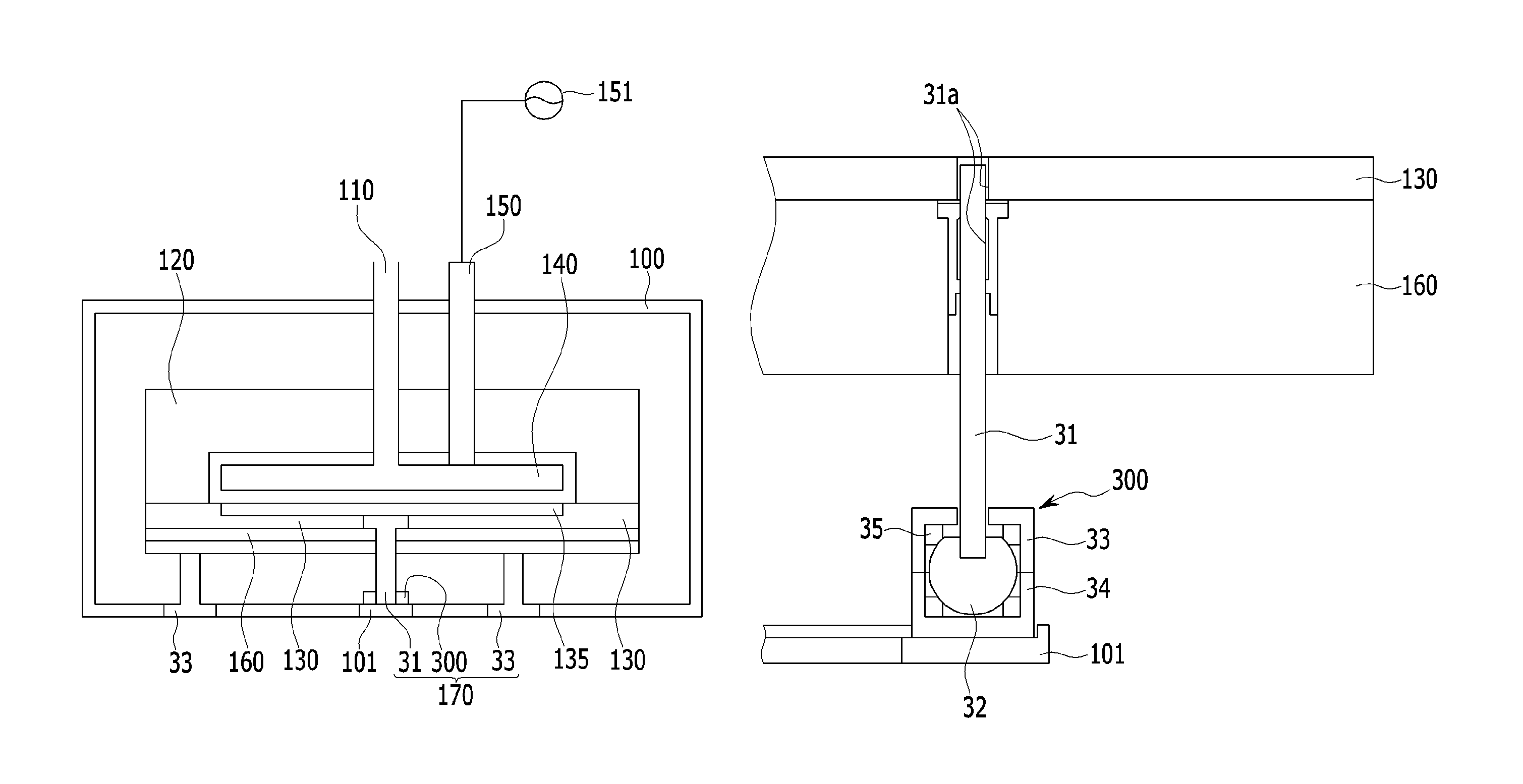
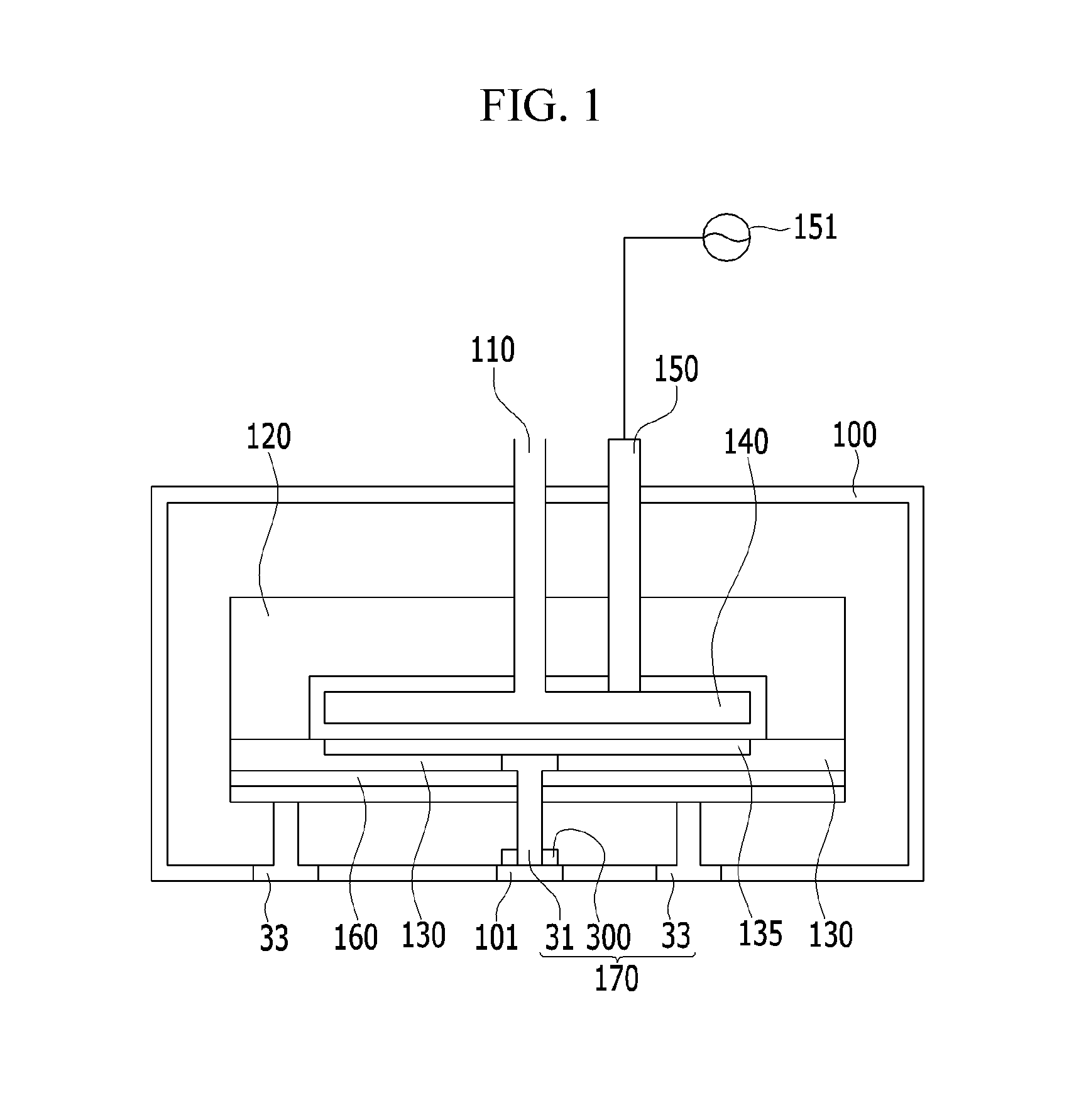
[0028]First, referring to FIG. 1, a deposition apparatus according to an exemplary embodiment of the ...


PUM

PropertyMeasurementUnit
weightaaaaaaaaaa
radiusaaaaaaaaaa
inner radiusaaaaaaaaaa

Abstract

A deposition apparatus includes a substrate supporting pin that is fixed to a supporting plate through an autoalignment control unit to prevent the substrate supporting pin from being broken when loading or unloading a substrate, thereby preventing damaging the substrate and also preventing decreased yield that may result due to the breakage of the substrate supporting pin.

Description

CROSS-REFERENCE TO RELATED APPLICATION[0001]This application claims priority to and the benefit of Korean Patent Application No. 10-2012-0086336 filed in the Korean Intellectual Property Office on Aug. 7, 2012, the entire contents of which are incorporated herein by reference.BACKGROUND OF THE INVENTION[0002](a) Field of the Invention[0003]The present invention relates to a deposition apparatus.[0004](b) Description of the Related Art[0005]In a deposition apparatus that is used to deposit a predetermined film on a silicon substrate, a substrate supporting pin or a substrate lift pin is used to load or unload a substrate before and after a process.[0006]The substrate supporting pin includes a fixed supporting pin and a non-fixed supporting pin. The fixed supporting pin has a shape of which a lower part of the substrate supporting pin is fixed to a lift pin supporter. In the case of the fixed supporting pin, the substrate supporting pin may be damaged due to friction with a lift pin h...

Claims


Application Information

Patent Timeline
Patent Type & Authority Patents(United States)
IPC IPC(8): B05C13/00H01L21/687C23C16/458
CPCB05C13/00C23C16/4583H01L21/68742C23C14/50
Inventor JEONG, SANG-JIN
Owner ASM IP HLDG BV
Why Eureka
Try Eureka